Author Topic: VIIC/41 - Schematices drawing  (Read 600624 times)

0 Members and 41 Guests are viewing this topic.

TRM

  • Guest
Re: VIIC/41 - Schematices drawing
« Reply #600 on: 04 Sep , 2010, 16:38 »
Great news everyone is fine. That is some heavy duty movement to shift a road 3m!!!!!  At least was it in the right direction, giving more frontage to the property. ;)

You prompted me to google your homeland.... :o!  Simply amazing corner of the world there.  I think I will add it to my bucket list of places to go.

 We "got lucky" with Evan, up here.  Thought I was going to get at least what we call a bad Nor' Easta' (north eastern driving storm with a crappy MA accent)....then nothing.  little rain and done.  The news was scaring everybody for a week we were going to get slammed.  Came in the night!  Sunny yesterday and sunny today.

Enjoy the skiing!

Cheers!


Offline SnakeDoc

  • Admiral
  • *
  • Posts: 536
  • Gender: Male
    • Torpedo Vorhaltrechner Project
Re: VIIC/41 - Schematices drawing
« Reply #601 on: 12 Sep , 2010, 14:38 »
Hi Simon

Does anyone have and seen a picture of the High pressure air bottles under the deck ???

Maybe this helps:
http://www.dailymotion.pl/video/xax1hd_uboot-767_tech
around 5,56 min.

--
Regards
Maciek

Offline NZSnowman

  • Admiral4
  • *
  • Posts: 2,419
  • Gender: Male
  • U-1308
    • U-1308 - Wikipedia
Re: VIIC/41 - Schematices drawing
« Reply #602 on: 12 Sep , 2010, 15:49 »
A very big thinks Maciek! :) :) I love to look at any pictures of the internal parts of the Type VII

Offline SnakeDoc

  • Admiral
  • *
  • Posts: 536
  • Gender: Male
    • Torpedo Vorhaltrechner Project
Re: VIIC/41 - Schematices drawing
« Reply #603 on: 13 Sep , 2010, 02:19 »
Hi Simon

Group A high pressure air bottles are seated much higher under the deck than I imagine. It looks like the drawing in David Westwood book was correct. Maybe seating the bottles this way was to let the water drain to the bottom of the bottle ???

I'm quite sure, that is for that reason - air, when compressed is heating up. Then, when is cooling down, the water vapor condenses.
I suppose, that there, in the lowest point of bottle, should be even some draining valve.

--
Regards
Maciek

Offline Rokket

  • Administrator
  • *
  • Posts: 2,362
  • Gender: Male
  • Submarine Enthusiast
    • AMP - Accurate Model Parts
Re: VIIC/41 - Schematices drawing
« Reply #604 on: 13 Sep , 2010, 16:07 »
Yes, BUT...I just found out that the USN Gatos had a 4-stage air compressor (well, 2 twins). This is the 3,000 pound air system (min 1500psi, max 4500).

They had chilling (well, cooling) at each stage so it wasn't roasting and wet. (One of the stages, I THINK the first, or maybe the 4th, was in the oil sump tray! To save space and have the oil (presumably) help transfer heat.

SO, it is possible there was a roughly similar (at least in overall function: "cool") to these babies...
AMP - Accurate Model Parts - http://amp.rokket.biz

Offline Pat

  • Captain
  • *
  • Posts: 395
Re: VIIC/41 - Schematices drawing
« Reply #605 on: 13 Sep , 2010, 17:49 »
Interesting bit of info Wink.  I can't figure out why the pump would be IN the oil sump though.  It wouldn't transfer that much heat that way, and it makes it harder to work on if there are repairs needed.

Is the hi-press air used in the inhabitable parts of the boat too, just going through a regulator to step down the pressure?  The reason why I'm wondering is that if there was a problem and oil got sucked into the lines, then it could result in vapourized oil in the air which couldn't be healthy.

Back to the German practice, if the compressed air WAS cooled during the process to take out water, what other reason would there be to have the tanks at such an angle?

Offline SnakeDoc

  • Admiral
  • *
  • Posts: 536
  • Gender: Male
    • Torpedo Vorhaltrechner Project
Re: VIIC/41 - Schematices drawing
« Reply #606 on: 14 Sep , 2010, 03:16 »
Well, related to Type IXC Design Study, section S49  -Compressed Air Plant description, both compressors were
connected to high pressure air installation via water separators and air filters.
http://uboatarchive.net/DesignStudiesTypeIXC.htm

Previous in this thread were attached photos of air flasks under the upper deck of Gato submarine - there were
even more inclined. Unfortunately, I was not able to find more detailed view.
I suppose, that despite of coolers and water separators, during each air recharging cycle
some vapor condensated. During each patrol there were many recharging cycles and the amount
of water in air flasks were significant, and some drain installation were necessery.

--
Regards
Maciek

Offline Pat

  • Captain
  • *
  • Posts: 395
Re: VIIC/41 - Schematices drawing
« Reply #607 on: 14 Sep , 2010, 17:35 »
I agree with you about all the recharging cycles during an patrol SnakeDoc.  And most diesel engines have water separators in the fuel line because the diurnal chilling causes any water in the air inside the fuel tank to condense and contaminate the fuel, so why not something similar with the boat diving into cold water and then surfacing into warm air?

At one time long ago, I drove a transport truck with air brakes, and it was SOP to bleed the water out of the air tanks every morning before starting up the engine.  I'm sure there must have been water filters/separators somewhere in the hi-press air lines of the truck, but there was still a concern to get any accumulation out of the tanks. 

So back in the early days of U-boats, it makes even more sense that they wouldn't have trusted the technology to get all the water out and would have some way of draining it just in case.

Offline Rokket

  • Administrator
  • *
  • Posts: 2,362
  • Gender: Male
  • Submarine Enthusiast
    • AMP - Accurate Model Parts
Re: VIIC/41 - Schematices drawing
« Reply #608 on: 18 Sep , 2010, 03:07 »
Pat - I KNOW it sounds strange, or like I have heard from polluted sources or not understood, but I was standing in the pump room touching the #2 compressor as the guy who rebuilt it explained everything. The sump seems an odd place, but it saved space. Sure, a pain to get to for repair, but not all that bad and they hoped repair wouldn't be nec in the field. The oil made an excellent temp transfer, increasing efficiency.

All the "strange" things this guy has encountered on fleetboats have proven to be well-reasoned to his astonishment.

I honestly don't know about il/water filtration, I'm assuming there was some, I only mentioned the cooling because it related and would certainly help.

There were 5 Fleetboat air systems:

1 - 3000lb main (not directly tied to anything)
2 - 600lb Ballast blow and torpedo firing (comes from 3000 reduced)
3 - 225lb service air (run tools at 100psi, blow various small tanks) (comes from 3000 reduced)
4 - 10lb (finish blowing ballast) (independent compressor)
5 - salvage air (salvage teams could tie in and blow water from a sunken boat or flooded compartments)

That's all I know!

Maciek - The Gato inclined flasks I have seen too, they seem to be inclined ONLY to conform to the hull casing (the "V" of the bow) - and were used for firing torps.
AMP - Accurate Model Parts - http://amp.rokket.biz

Von Hilde

  • Guest
Re: VIIC/41 - Schematices drawing
« Reply #609 on: 18 Sep , 2010, 04:25 »
actually it prevents the boat from steering off a straight line:
given that the pressure is different on top and bottom of the screw, it gives the stern the tendency to steer to the right with a clockwise rotation of the screw.
usefull when you want to bring the stern to the quay........

  the torque is reffered to as, P factor. This is also applied to aircraft. Dual props that are counter rotating cancel out this. On a single engine aircraft it is nessissary to counter this effect, by applying rudder in the direction of the rotation of the prop as the torque is in the opposie direction of the rotation and has the tendency to direct the heading in that direction

Offline NZSnowman

  • Admiral4
  • *
  • Posts: 2,419
  • Gender: Male
  • U-1308
    • U-1308 - Wikipedia
Re: VIIC/41 - Schematices drawing
« Reply #610 on: 21 Sep , 2010, 20:30 »
I had been working on the wintergarten platforms for U-1308 for the last few months. During this time I see a good portion of pictures of Type VIIC

Offline NZSnowman

  • Admiral4
  • *
  • Posts: 2,419
  • Gender: Male
  • U-1308
    • U-1308 - Wikipedia
Re: VIIC/41 - Schematices drawing
« Reply #611 on: 22 Sep , 2010, 18:53 »


U-1308 gets it Wintergarten platforms and bridge.

http://img638.imageshack.us/img638/5278/wintergartenplatforms.jpg (Drawing 100%)
« Last Edit: 22 Sep , 2010, 19:01 by NZSnowman »

Offline NZSnowman

  • Admiral4
  • *
  • Posts: 2,419
  • Gender: Male
  • U-1308
    • U-1308 - Wikipedia
Re: VIIC/41 - Schematices drawing
« Reply #612 on: 23 Sep , 2010, 22:59 »
Does anyone have any pictures of any piping under the Wintergarten platforms and bridge?

Or...

Does anyone have any pictures of any piping under the main deck?

Offline NZSnowman

  • Admiral4
  • *
  • Posts: 2,419
  • Gender: Male
  • U-1308
    • U-1308 - Wikipedia
Re: VIIC/41 - Schematices drawing
« Reply #613 on: 24 Sep , 2010, 21:41 »
Does anyone have any good pictures of the Flooding/blowing vents on top of the saddle tanks?

Offline Rokket

  • Administrator
  • *
  • Posts: 2,362
  • Gender: Male
  • Submarine Enthusiast
    • AMP - Accurate Model Parts
Re: VIIC/41 - Schematices drawing
« Reply #614 on: 25 Sep , 2010, 01:49 »
no to all, this last one - there are a couple (or 1?) shot(s) in the Anatomy of a VIIC book. The Brits have captured a uboat and are working on it at dock, and the saddle tank covers are pretty prominent.
AMP - Accurate Model Parts - http://amp.rokket.biz

Offline NZSnowman

  • Admiral4
  • *
  • Posts: 2,419
  • Gender: Male
  • U-1308
    • U-1308 - Wikipedia
Re: VIIC/41 - Schematices drawing
« Reply #615 on: 09 Oct , 2010, 20:06 »
I nearly finishing my research on the saddle tank hatches today. I apology to Dougie and Pat for misleading them about the differences in the shape of the hatches. http://models.rokket.biz/index.php?topic=124.msg6627#msg6627 As it has turn out that were are two different shapes hatches. There are five hatches along the saddle tank (Fig. 1).


Fig. 1. Hatch 1 to 5 - Stern to bow.

I am almost certain there is only one vent valve and this is Hatch 3 as illustrate in the plan below. Also there is no internal arms system to open this valve, you would need to be on the surface to open and closed it.

from uboatarchive.net http://www.uboatarchive.net/U-570Plate16.htm

Hatches
Hatch 1 access to Main ballast and reserve fuel oil tank 2
Hatch 2 access to reg. tanks and reserve fuel oil tank 1
Hatch 3 Vent valve for reg. tank 2
Hatch 4 access to Neg. buoyancy tank
Hatch 5 access to Main ballast and reserve fuel oil tank 4

By using the patches of the missing hatches on U-995 and counting the frames and was able to place the hatches in there correct locations. Below is a list of the real distance between the end of the stern to the centre of the hatch. If your model is 1:72 scale just divide the number by 72.

Distance
Hatch 1 27,750 mm
Hatch 2 30,250 mm
Hatch 3 33,750 mm
Hatch 4 35,275 mm
Hatch 5 37,350 mm

Size and shape
Hatch 1 about 60% sure on the shape and orientation, but should be 550mm by 400mm in size. I have not clear pictures of this hatch.
Hatch 2 not 100% sure on the shape or orientation but likely 550mm by 400mm in size. I have not clear pictures of this hatch.
Hatch 3 400mm - Circle
Hatch 4 400mm by 550mm in size.
Hatch 5 400mm by 550mm in size.

As yet I have seen no different between any VIIC
« Last Edit: 13 Jan , 2013, 10:55 by NZSnowman »

Offline Rokket

  • Administrator
  • *
  • Posts: 2,362
  • Gender: Male
  • Submarine Enthusiast
    • AMP - Accurate Model Parts
Re: VIIC/41 - Schematices drawing
« Reply #616 on: 10 Oct , 2010, 00:57 »
Fig 4 is gold! See, there always seems to be a mix of round and oval - the Brit pic I was talking about pretty clearly shows round, and this is a mix. Interesting. Wish I had these a few yrs ago!
AMP - Accurate Model Parts - http://amp.rokket.biz

Offline NZSnowman

  • Admiral4
  • *
  • Posts: 2,419
  • Gender: Male
  • U-1308
    • U-1308 - Wikipedia
Re: VIIC/41 - Schematices drawing
« Reply #617 on: 10 Oct , 2010, 13:05 »
Yes you are total right about figure four being the key for the whole hatch system on the saddle tanks. You can clearly see the round shape of the vent valve and I can just make out an outline of the inner plate also. The picture also give me the idea about the smooth outer cover, as you could clearly see the bolts to fix the cover plate to, but so many photographs either show a smooth surface over the hatches or a hollow. Then I realise that there must be a smooth second cover.

Still love to get a good photograph of hatch 1 and 2 to be 100% sure about the shape and orientation to finish of the research. Does anyone have any pictures of the hatches on the saddle tanks?

It seem many of the solution of the unsolved puzzles left with U-Boats we found over the last few years have come from either one or two key photographs. 


Offline dougie47

  • Administrator
  • *
  • Posts: 758
Re: VIIC/41 - Schematices drawing
« Reply #618 on: 10 Oct , 2010, 15:37 »
Hi Simon,

This is fantastic stuff, you've really taken this forward. I'll need a few days to digest properly and will get back to you.

Thanks,

Dougie

Offline dougie47

  • Administrator
  • *
  • Posts: 758
Re: VIIC/41 - Schematices drawing
« Reply #619 on: 12 Oct , 2010, 13:26 »
Hi Simon,

Thanks for all your research on the vents/covers...very interesting! I was wrong about the orientation on 3 and 4 - I think you are right about number 3 being circular. I've had a chance to look at photos properly and it does look circular right enough.

I'm fairly certain that number 4 was also a circle. Could number 4 be a Vent valve for reg. tank 1?


In the above two photos, I think the green arrow points to #3, red to #4, blue to #5.

Notice also that #3 may be closer towards the centreline of the boat than #4 (the weld seam goes through #3 but not #4)?


#2 and #3 can be seen in the image above.


Sorry about the quality of the image above, from P15 of Wetzel's U 995 book. In this photo in Wetzel's book, #3 and #4 really do look circular, the rest look oval.

I used to think there were 5 covers, but it bothered me a bit because 5 seemed too many. I think 2 vents and 3 covers per side is more plausible.

The covers would be oval shaped as it allows for a crewman to fit through. The vents don't need to be oval, hence I presume the round shape. 

Cheers,

Dougie

Offline NZSnowman

  • Admiral4
  • *
  • Posts: 2,419
  • Gender: Male
  • U-1308
    • U-1308 - Wikipedia
Re: VIIC/41 - Schematices drawing
« Reply #620 on: 12 Oct , 2010, 14:24 »

Vent valve; Hull opening (left), Inner hatch cover (middle) & Outer hatch cover (right).

Hull Opening: I have no idea that the valve look like under this hatch, however, the valve allows sea water in to the tank. I just used a frequent used valve on the boat and an open ended pipe.
Inner Hatch Cover: In the middle of this cover, you can see a smaller access hatch, I imagine it for quick access to the vent below :-\ Unsure what six pins do as seen in figure 4 of the previous posting. In the photograph below you can see what I believe is the under side of the outer hatch. There seem to be a rise support ridge on the base of this cover, perhaps the six pens lock into matching holes on base ???


Just was just about post my second part of my research then flash a warning

Seewolf

  • Guest
Re: VIIC/41 - Schematices drawing
« Reply #621 on: 12 Oct , 2010, 20:51 »
Hi Simon great work with the saddle tanks, slowly everything comes together  ;D

Offline NZSnowman

  • Admiral4
  • *
  • Posts: 2,419
  • Gender: Male
  • U-1308
    • U-1308 - Wikipedia
Re: VIIC/41 - Schematices drawing
« Reply #622 on: 13 Oct , 2010, 01:15 »
A update on the drawing, now includes the Saddle Tank Hatches


Key for Drawing
http://www.mediafire.com/?ign98y2vc981py8


Offline dougie47

  • Administrator
  • *
  • Posts: 758
Re: VIIC/41 - Schematices drawing
« Reply #623 on: 13 Oct , 2010, 13:39 »
Hi Simon,

Yeah, I hate it when that warning comes up! I've had a quick look at your latest drawing. The size, location and shape all look really good to me.

That's a good colour photo you posted. I've never seen the hatch in the open position, as it is in the photo. Well spotted.

Keep up the good work.

Cheers,

Dougie


Offline NZSnowman

  • Admiral4
  • *
  • Posts: 2,419
  • Gender: Male
  • U-1308
    • U-1308 - Wikipedia
Re: VIIC/41 - Schematices drawing
« Reply #624 on: 14 Oct , 2010, 15:07 »
Why did they change from bronze propellers to steel propellers from about January 1942 ???

Edit
Was it because of bronze shortage ???
« Last Edit: 14 Oct , 2010, 15:17 by NZSnowman »

Offline Pat

  • Captain
  • *
  • Posts: 395
Re: VIIC/41 - Schematices drawing
« Reply #625 on: 14 Oct , 2010, 21:41 »
I've spent a couple of hours looking for any advantages of stainless steel propellors over bronze and so far haven't found much.  It seems that bronze is a much better material for boat propellors than stainless steel, being cheaper, lighter, less brittle, easier to repair and having a lower friction coefficient.

So the only thing left that makes sense would be a shortage of bronze midway through the war.  Since England is known for large deposits of tin even since prehistoric times, it was likely a lack of tin that was the problem.  Tin is alloyed with copper to make bronze.

I can verify that bronze is better.  About 15 years ago, my propellor, which is bronze, got nicked by hitting a floating tire with a steel wheel inside.  I was able to get the propellor repaired quite easily.  I've been told that with similar damage to a stainless steel propellor it would have been a write-off.

If you're building a boat with a bronze propellor, the colour should be flat bronze, almost, but not quite oxidized to a pale green.  Think of the green of copper roofs but not so bright and mixed with a light brown.  Boat propellors do not go as dark as bronze statues but maintain a slight beige-orange-yellow hue in with the green.

If modelling a stainless steel propellor, it should be silver but shinier than a silver coin.  Almost, but not quite, mirror-like.  Think of the colour of a kitchen knife and almost as shiny.  Stainless steel props do not go flat unless in extremely sandy conditions.
« Last Edit: 14 Oct , 2010, 22:03 by Pat »

Offline NZSnowman

  • Admiral4
  • *
  • Posts: 2,419
  • Gender: Male
  • U-1308
    • U-1308 - Wikipedia
Re: VIIC/41 - Schematices drawing
« Reply #626 on: 14 Oct , 2010, 22:12 »
Pat, do you think that late war u-boats had stainless steel or steel propellors ??? Or where the talk about steel propellors they always talking about stainless steel ???

Offline Greif

  • Admiral2
  • *
  • Posts: 755
  • Gender: Male
Re: VIIC/41 - Schematices drawing
« Reply #627 on: 15 Oct , 2010, 02:14 »
Just wanted to say hi Simon!  Its been a while since my last post.  I had a very busy racing season in road cycling and did not get online much between the beginning of April and now.  You drawings are top notch as always.  How did the ski season go in NZ?

Ernest

Offline Pat

  • Captain
  • *
  • Posts: 395
Re: VIIC/41 - Schematices drawing
« Reply #628 on: 15 Oct , 2010, 07:02 »
Welcome back Ernest.  Nice to see you again.

Simon, I'm almost sure that whenever it says 'steel' for propellors, it means 'stainless steel'.

Regular steel is not desirable for ship's propellors because it quickly gets pitted from electrolysis and coated with rust.  This would particularly bad for submursibles because the way surface ships locate them is by acoustics (ASDIC for the Commonwealth, Sonar for the Americans).  Any pitting or rust buildup not only reduces the propellor efficiency, but it also causes cavitation - the formation of air bubbles that causes more propellor noise even at slow speeds.  (Cavitation is also the cause of the reduced efficiency, as the prop loses its driving power when it's turning through gas instead of water).

Also, marine organisms like barnacles will adhere to steel propellors but they can't stick to stainless steel or bronze.

Because of their speed through the water, propellors don't hold antifouling paint.  It just wears off in a matter of a couple hundred nautical miles.  The paint itself then also creates cavitation with the roughness between the worn and the unworn parts.  Usually the leading edge is where it polishes clean first.

Offline dougie47

  • Administrator
  • *
  • Posts: 758
Re: VIIC/41 - Schematices drawing
« Reply #629 on: 20 Oct , 2010, 08:37 »
Hi Simon,

This photo might help with the treadplate on the lower part of the UZO-

http://cgi.ebay.de/Orig-Foto-U-Bootfahrer-U-Boot-635-Kapitan-Eckelmann-/380279884991?pt=Militaria&hash=item588a728cbf

Cheers,

Dougie

Offline NZSnowman

  • Admiral4
  • *
  • Posts: 2,419
  • Gender: Male
  • U-1308
    • U-1308 - Wikipedia
Re: VIIC/41 - Schematices drawing
« Reply #630 on: 20 Oct , 2010, 12:33 »
Hi Dougie

Many thanks for the picture  :) :)

It looks to me like a lattice of Arc welding lines to me. I have seem this at work there they Arc welding lines in a mesh hatching pattern to a excavator buckets to slow down the wearing down of it (see picture below). It look like the Germans used the same system on this tread plate, to add grip for standing and to slow wear of the plate  :-\

Simon


Offline dougie47

  • Administrator
  • *
  • Posts: 758
Re: VIIC/41 - Schematices drawing
« Reply #631 on: 20 Oct , 2010, 13:27 »
Hi Simon,

Yeah, the lattice on your photo looks the same as the U-boat photo. Notice that the UZO plate isn't entirely round. There is a semi-circular chunk missing (near the top right of the photo).

Cheers,

Dougie

Offline NZSnowman

  • Admiral4
  • *
  • Posts: 2,419
  • Gender: Male
  • U-1308
    • U-1308 - Wikipedia
Re: VIIC/41 - Schematices drawing
« Reply #632 on: 20 Oct , 2010, 13:47 »
Dougie, yes, I did notice the notch, but now that you made me think a little more about it. I seen this before on a few boat. I will have to recheck my pictures and see if there a pattern to this.

Also I just notice that the deck is metal. I sure they move to wood near the end of the war :-\

LE BOSCO

  • Guest
Re: VIIC/41 - Schematices drawing
« Reply #633 on: 21 Oct , 2010, 14:30 »
Hi Simon

On the photo(U-635)It is of the anti-skid striated sheet steel !not in arc welding ,The features are too regular
I am metallic carpenter of formation (and locksmith, blacksmith now)
regards
Nico

Offline NZSnowman

  • Admiral4
  • *
  • Posts: 2,419
  • Gender: Male
  • U-1308
    • U-1308 - Wikipedia
Re: VIIC/41 - Schematices drawing
« Reply #634 on: 21 Oct , 2010, 14:52 »
Hi Nicolas,

You are correct about the features being very regular for wielding. Relooking at the picture, even the thickness of the lines are very regular.  One question rises, how did they add the anti-skid pattern, do the roll in the pattern while the steel is hot?

Simon

LE BOSCO

  • Guest
Re: VIIC/41 - Schematices drawing
« Reply #635 on: 21 Oct , 2010, 15:01 »
the roll in the pattern while the steel is hot?

Simon


yes Simon

The sheet of steel , in the red ,is spent between two rollers, among which one with the negative of striated !  As with a mould has waffle :D
Nicolas

Offline NZSnowman

  • Admiral4
  • *
  • Posts: 2,419
  • Gender: Male
  • U-1308
    • U-1308 - Wikipedia
Re: VIIC/41 - Schematices drawing
« Reply #636 on: 22 Oct , 2010, 11:32 »
Just wanted to say hi Simon!  Its been a while since my last post.  I had a very busy racing season in road cycling and did not get online much between the beginning of April and now.  You drawings are top notch as always.  How did the ski season go in NZ?

Ernest

I had little time this week to work on U-1308 as I am busy writing my end of winter weather report. Yesterday I got to the point that I need a break, so I decided to reinstall an old computer game

Offline Rokket

  • Administrator
  • *
  • Posts: 2,362
  • Gender: Male
  • Submarine Enthusiast
    • AMP - Accurate Model Parts
Re: VIIC/41 - Schematices drawing
« Reply #637 on: 23 Oct , 2010, 16:55 »
Funny stuff! Not as nice as yours, but not bad for a game1
AMP - Accurate Model Parts - http://amp.rokket.biz

Offline Pepper-mint

  • Commander
  • *
  • Posts: 343
  • Gender: Male
  • U-1299
Re: VIIC/41 - Schematices drawing
« Reply #638 on: 24 Oct , 2010, 06:07 »
NZ, you can't escape from studying a u-boat plan ! Even in your game  ;D ;D ;D
On the W.bench :
Books, pics, drawings, styrene, dreams and :

Offline Greif

  • Admiral2
  • *
  • Posts: 755
  • Gender: Male
Re: VIIC/41 - Schematices drawing
« Reply #639 on: 25 Oct , 2010, 00:18 »
Hi Simon, sounds like NZ had a mega-winter like Germany's past winter.  The winter of 09-10 had the most snow since 1979-80.  I hope we get a fair amount of snow this year also, as I want to try out snowshoeing as a fitness sport.  We shall see. 

Funny how games sometimes remind us of projects we are working on.  ;D

All the Best,
Ernest

Just wanted to say hi Simon!  Its been a while since my last post.  I had a very busy racing season in road cycling and did not get online much between the beginning of April and now.  You drawings are top notch as always.  How did the ski season go in NZ?

Ernest

I had little time this week to work on U-1308 as I am busy writing my end of winter weather report. Yesterday I got to the point that I need a break, so I decided to reinstall an old computer game

Offline NZSnowman

  • Admiral4
  • *
  • Posts: 2,419
  • Gender: Male
  • U-1308
    • U-1308 - Wikipedia
Re: VIIC/41 - Schematices drawing
« Reply #640 on: 27 Oct , 2010, 02:53 »
Does anyone know what colour the fuel oil was on the U-Boats?


Offline SnakeDoc

  • Admiral
  • *
  • Posts: 536
  • Gender: Male
    • Torpedo Vorhaltrechner Project
Re: VIIC/41 - Schematices drawing
« Reply #641 on: 27 Oct , 2010, 03:21 »
Hi Simon

Does anyone know what colour the fuel oil was on the U-Boats?

Maybe this helps:
http://www.fischer-tropsch.org/primary_documents/gvt_reports/USNAVY/usnavy-europe_toc.htm

better than nothing...

--
Regards
Maciek

Offline Pat

  • Captain
  • *
  • Posts: 395
Re: VIIC/41 - Schematices drawing
« Reply #642 on: 27 Oct , 2010, 06:52 »
Where in the list does it give the colour of the diesel SnakeDoc?

Perhaps it might help Simon, if we knew why you wnated the colour of the diesel fuel.  Like most transparent liquids, it would appear different depending on how it's being viewed (through a clear hose or looking inside a deep tank) or how long it's been sitting (older fuel tends to get darker with age).

My guess is that it would be about the same colour as diesel fuel is today.  That is to say that there would be some variation depending on the manufacturer and what colouration they might be intentionally adding to it.

The diesel I've gotten for my boat seems to vary from almost colourless with a slight hint of amber or yellow) at some gas stations (say at Shell for example) to a darker, almost honey-coloured liquid at others (Esso for example) but I've really never paid it much attention.  Most of the time I only see it if I spill it, since it goes directly into the container from the hose and then into the fuel tank on the boat, hopefully never seeing the light of day.  It's an awful smell, as I found out when I spilled a couple of litres in my bilge more than a decade ago and it took about 5 or 6 years to get the smell out of the boat, even using all sorts of environmental cleansing agents.

SnakeDoc's link mentions Kogasin, which I presume must be a smei-synthetic distillate of crude oil having a  iodine in it, which might give it a darker tint, but I'd guess that if you use a honey colour, you'd be about right.   Keeping in mind that "honey" is also a vague term for colour, since honey can vary from almost clear to a dark amber, so in it would be just about right.


Offline SnakeDoc

  • Admiral
  • *
  • Posts: 536
  • Gender: Male
    • Torpedo Vorhaltrechner Project
Re: VIIC/41 - Schematices drawing
« Reply #643 on: 27 Oct , 2010, 07:25 »
Where in the list does it give the colour of the diesel SnakeDoc?

Well,
"Technical Report No.333-45: German Naval Fuel Oil"
http://www.fischer-tropsch.org/primary_documents/gvt_reports/USNAVY/tech_rpt_333_45/Report-333-45.pdf
on page 11 there is a table "Properties of german fuel oil components" with first row labeled as color (in Ostwald color system).

--
Regards
Maciek

Offline SnakeDoc

  • Admiral
  • *
  • Posts: 536
  • Gender: Male
    • Torpedo Vorhaltrechner Project
Re: VIIC/41 - Schematices drawing
« Reply #644 on: 27 Oct , 2010, 08:30 »
To forestall another allegations - it seems that to get final color described by index "10" there is needed "Color harmony manual" by Egbert Jacobson, Walter C. Granville and Carl E. Foss.


--
Regards
Maciek

Offline NZSnowman

  • Admiral4
  • *
  • Posts: 2,419
  • Gender: Male
  • U-1308
    • U-1308 - Wikipedia
Re: VIIC/41 - Schematices drawing
« Reply #645 on: 27 Oct , 2010, 11:20 »
Hi Maciek & Pat

Thanks both for all your help with the fuel oil :) :)

Maciek, a great report, where do you keep finding there fantastic little reports from? I keep thinking I seen them all?

The reason why I was asking about the colour of the fuel oil was, yesterday while studying the general layout of the Senior Raters section of the Type VII

Offline NZSnowman

  • Admiral4
  • *
  • Posts: 2,419
  • Gender: Male
  • U-1308
    • U-1308 - Wikipedia
Re: VIIC/41 - Schematices drawing
« Reply #646 on: 31 Oct , 2010, 01:12 »
Does anyone know what was inside the

Offline Pat

  • Captain
  • *
  • Posts: 395
Re: VIIC/41 - Schematices drawing
« Reply #647 on: 31 Oct , 2010, 08:49 »
Beyond the obvious, that there's a main battery switch there, no.  I know more about the inside of a U-boat with great thanks to your drawings than from any other source.

What I can say is that a modern surface boat usually has a battery switch that isolates certain batteries (or in the case of a U-boat, would isolate entire banks of batteries) so that you can draw power from one battery while the other(s) are either being serviced, charged or restricted to other purposes.

For instance, on my boat, I'll usually start/run the engine with one battery while I reserve the other battery for the electronics.  The reason for that is that it ensures that if I run down a battery through electronics, I'll have a freshly charged battery available still for emergency starting/navigating.distress call.  On alternate days, I switch which battery does which job so that one is always being charged.

The main switch can also join ALL batteries together at once for a heavy use (off, battery one, all, battery two) but you usually wouldn't run both together since the fresher battery will always hog the charge from the alternator (magneto on a sub?) and not distribute it evenly over both batteries.

The 'off' position is used when the boat is in port and not being used because there is a tendency for boats (and this would be worse for a steel-hulled boat) of power leakage and galvanic action with anything in the water, so you turn the batteries off when not needed to minimize this risk.

That's also the reason for the zincs on the aft dive planes, rudders and prop shaft supports that we talked about in a past exchange.

I'd guess that the main switch on a U-boat would function in a similar way but be more complex since there are many more batteries involved and the systems are more critical.  Probably it would have more settings and more possible ways of hooking up the batteries together?

One more thing is that every battery switch I've ever seen on a boat has always been a fire-engine red.  Don't know if that would necessarily be the case with WWII U-boats, but it seems likely.

Offline NZSnowman

  • Admiral4
  • *
  • Posts: 2,419
  • Gender: Male
  • U-1308
    • U-1308 - Wikipedia
Re: VIIC/41 - Schematices drawing
« Reply #648 on: 31 Oct , 2010, 18:18 »
Beyond the obvious, that there's a main battery switch there, no.  I know more about the inside of a U-boat with great thanks to your drawings than from any other source.

What I can say is that a modern surface boat usually has a battery switch that isolates certain batteries (or in the case of a U-boat, would isolate entire banks of batteries) so that you can draw power from one battery while the other(s) are either being serviced, charged or restricted to other purposes.

For instance, on my boat, I'll usually start/run the engine with one battery while I reserve the other battery for the electronics.  The reason for that is that it ensures that if I run down a battery through electronics, I'll have a freshly charged battery available still for emergency starting/navigating.distress call.  On alternate days, I switch which battery does which job so that one is always being charged.

The main switch can also join ALL batteries together at once for a heavy use (off, battery one, all, battery two) but you usually wouldn't run both together since the fresher battery will always hog the charge from the alternator (magneto on a sub?) and not distribute it evenly over both batteries.

The 'off' position is used when the boat is in port and not being used because there is a tendency for boats (and this would be worse for a steel-hulled boat) of power leakage and galvanic action with anything in the water, so you turn the batteries off when not needed to minimize this risk.

That's also the reason for the zincs on the aft dive planes, rudders and prop shaft supports that we talked about in a past exchange.

I'd guess that the main switch on a U-boat would function in a similar way but be more complex since there are many more batteries involved and the systems are more critical.  Probably it would have more settings and more possible ways of hooking up the batteries together?

One more thing is that every battery switch I've ever seen on a boat has always been a fire-engine red.  Don't know if that would necessarily be the case with WWII U-boats, but it seems likely.

Thanks Pat, all great information!! :) :) Will help a lot!! I hope I am able to get one picture from the inside. It will drive me crazy not knowing that inside for my drawing. It extremely important to me, to get the drawing accurate. That why I put in the time to make the smallest detail correct, like the German Kriegsmarine china tableware set ;D, the ship clock, all the piping or the framing and ribbing etc

Offline NZSnowman

  • Admiral4
  • *
  • Posts: 2,419
  • Gender: Male
  • U-1308
    • U-1308 - Wikipedia
Re: VIIC/41 - Schematices drawing
« Reply #649 on: 31 Oct , 2010, 18:23 »
I can not imagine that these taps are the original German taps, does anyone know what they would look like? (Or are they the original tap?)

Thanks, Simon.


Picture from http://www.u-historia.com/

« Last Edit: 31 Oct , 2010, 21:24 by NZSnowman »

Offline NZSnowman

  • Admiral4
  • *
  • Posts: 2,419
  • Gender: Male
  • U-1308
    • U-1308 - Wikipedia
Re: VIIC/41 - Schematices drawing
« Reply #650 on: 01 Nov , 2010, 14:24 »
Does anyone have "Vom Original zum Modell, Uboottyp VII C" by Fritz K

Offline dougie47

  • Administrator
  • *
  • Posts: 758
Re: VIIC/41 - Schematices drawing
« Reply #651 on: 01 Nov , 2010, 15:04 »
Hi Simon,

"Vom Original zum Modell, Uboottyp VII C" by Fritz K

Offline NZSnowman

  • Admiral4
  • *
  • Posts: 2,419
  • Gender: Male
  • U-1308
    • U-1308 - Wikipedia
Re: VIIC/41 - Schematices drawing
« Reply #652 on: 01 Nov , 2010, 16:51 »
Hi Dougie.

Yes I have seen all the plans and a few extra ones. I was trying to found a little about the history of these plans. How they were found and redrawn. I believe they were found sometime after the war (60

Offline NZSnowman

  • Admiral4
  • *
  • Posts: 2,419
  • Gender: Male
  • U-1308
    • U-1308 - Wikipedia
Re: VIIC/41 - Schematices drawing
« Reply #653 on: 01 Nov , 2010, 20:15 »
A small update today for the outlets valves for Diving Tank 3. I found this picture from http://www.u-boot-zentrale.de/eng/tower.htm with a wire net to protect against foreign bodies entering the tank.


Offline NZSnowman

  • Admiral4
  • *
  • Posts: 2,419
  • Gender: Male
  • U-1308
    • U-1308 - Wikipedia
Re: VIIC/41 - Schematices drawing
« Reply #654 on: 01 Nov , 2010, 21:28 »
Why did they change from bronze propellers to steel propellers from about January 1942 ???

Edit
Was it because of bronze shortage ???

I've spent a couple of hours looking for any advantages of stainless steel propellors over bronze and so far haven't found much.  It seems that bronze is a much better material for boat propellors than stainless steel, being cheaper, lighter, less brittle, easier to repair and having a lower friction coefficient.

So the only thing left that makes sense would be a shortage of bronze midway through the war.  Since England is known for large deposits of tin even since prehistoric times, it was likely a lack of tin that was the problem.  Tin is alloyed with copper to make bronze.

I can verify that bronze is better.  About 15 years ago, my propellor, which is bronze, got nicked by hitting a floating tire with a steel wheel inside.  I was able to get the propellor repaired quite easily.  I've been told that with similar damage to a stainless steel propellor it would have been a write-off.

If you're building a boat with a bronze propellor, the colour should be flat bronze, almost, but not quite oxidized to a pale green.  Think of the green of copper roofs but not so bright and mixed with a light brown.  Boat propellors do not go as dark as bronze statues but maintain a slight beige-orange-yellow hue in with the green.

If modelling a stainless steel propellor, it should be silver but shinier than a silver coin.  Almost, but not quite, mirror-like.  Think of the colour of a kitchen knife and almost as shiny.  Stainless steel props do not go flat unless in extremely sandy conditions.

Had to update U-1308 propellers to the correct time period (sad as I like the look of the bronze propellers better :'( ).

Pat, was searching the net for pictures today for stainless steel propellers, your right about the stainless steel keeping there colours. Also found this picture, WOW! :o That one big U-Boat  ;D ;)


Offline SnakeDoc

  • Admiral
  • *
  • Posts: 536
  • Gender: Male
    • Torpedo Vorhaltrechner Project
Re: VIIC/41 - Schematices drawing
« Reply #655 on: 02 Nov , 2010, 10:41 »
Hi Simon

Does anyone know what was inside the

Offline Greif

  • Admiral2
  • *
  • Posts: 755
  • Gender: Male
Re: VIIC/41 - Schematices drawing
« Reply #656 on: 02 Nov , 2010, 11:56 »
Does anyone know what was inside the

Offline NZSnowman

  • Admiral4
  • *
  • Posts: 2,419
  • Gender: Male
  • U-1308
    • U-1308 - Wikipedia
Re: VIIC/41 - Schematices drawing
« Reply #657 on: 02 Nov , 2010, 12:59 »
That would be wonderful, thanks.

Offline NZSnowman

  • Admiral4
  • *
  • Posts: 2,419
  • Gender: Male
  • U-1308
    • U-1308 - Wikipedia
Re: VIIC/41 - Schematices drawing
« Reply #658 on: 04 Nov , 2010, 20:13 »
I have just found a significant error on Plan 11c of ‘Fritz Köhl & Axel Niestle U-Boat Type VIIC plans’ with the measurements of the search periscope. They list a total length of the search periscope as 9300 mm it should be 7825.5 mm, a huge different!! Any of my drawing with the search periscope previous to this date will be incorrect >:(

For modelling, if you want to extended your periscopes to there maximum used these figures:

Attack periscope - bottom of keel to top of periscope = 14663 mm (204 mm at 1:72 scale)
Search periscope - bottom of keel to top of periscope = 11999 mm (167 mm at 1:72 scale)

If a error like this could happen; it may help to example how the other error I have found with the high/low air lines happen.

.... I was trying to found a little about the history of these plans. How they were found and redrawn. I believe they were found sometime after the war (60’s  ???) and redrawn during the 80’s and 90’s. The reason why I am after this information is, over the last two or three weeks I been doing a lot of research on the high/low air lines that run under the deck but outside the pressure hull. I have looked at numerous sets of plans, schematises drawing and photographs and this morning I came to the conclusion that the air lines drawn on these set of plans are almost useless. They are inaccurate, and most lines are absent, so air lines are drawn in area there are no hull openings or just does not make sense to put them there.
I was trying to found how the errors happen. Did it happen while redrawing, or are the errors on the original plans? I mostly believe the errors happen while redrawing. Likely the original plans were very hard to read and a few air lines were missed or so lines were assume to be air lines but were in fact, other systems.

Offline Pat

  • Captain
  • *
  • Posts: 395
Re: VIIC/41 - Schematices drawing
« Reply #659 on: 04 Nov , 2010, 21:14 »
Simon, those measurements for the periscopes don't seem right.

When you look at the top of the CT, the tops of both persicopes in their 'down' position are level with each other.  If that's the case, then they can't be different if they both go to the keel.

That might be the correct length for each tube, but only if the search periscope doesn't go all the way to the keel.  (In point of fact, I don't think it does go down as far.)

Offline NZSnowman

  • Admiral4
  • *
  • Posts: 2,419
  • Gender: Male
  • U-1308
    • U-1308 - Wikipedia
Re: VIIC/41 - Schematices drawing
« Reply #660 on: 04 Nov , 2010, 21:55 »
Hi Pat, I mean if the periscopes are extended to there maximum height. The distance from the bottom of the keel to the very top on the periscopes will be these figures. In the drawing below the
« Last Edit: 04 Nov , 2010, 22:41 by NZSnowman »

Offline NZSnowman

  • Admiral4
  • *
  • Posts: 2,419
  • Gender: Male
  • U-1308
    • U-1308 - Wikipedia
Re: VIIC/41 - Schematices drawing
« Reply #661 on: 05 Nov , 2010, 01:30 »
Several weeks back I was so sick at looking at piping plans, I had to working on anything but piping. So I decided to draw the galley. Below are the results. Happy viewing.


Offline Pat

  • Captain
  • *
  • Posts: 395
Re: VIIC/41 - Schematices drawing
« Reply #662 on: 05 Nov , 2010, 06:42 »
Yes, that makes more sense now.  Thanks Simon.

Offline NZSnowman

  • Admiral4
  • *
  • Posts: 2,419
  • Gender: Male
  • U-1308
    • U-1308 - Wikipedia
Re: VIIC/41 - Schematices drawing
« Reply #663 on: 05 Nov , 2010, 15:57 »
I love it when your research comes together. Even the smallest things can make me happy ;D Plus it all adds more detail to the big u-boat picture and increase the accurately of my drawing.

I have always believed that all the pipes under the deck were attached to the deck framing. This morning I noticed a pipe bracket I had not seen before in a picture from a Type IX. I have very few pictures of under the deck for Type VII

Offline NZSnowman

  • Admiral4
  • *
  • Posts: 2,419
  • Gender: Male
  • U-1308
    • U-1308 - Wikipedia
Re: VIIC/41 - Schematices drawing
« Reply #664 on: 06 Nov , 2010, 02:50 »
Below is a cross-section of the exhaust outlet valves from the diesel motor. The yellow circle is the trunk line however, there look to be an outer shell around the trunk line (red) and a space between them. Does anyone know if they water cool the hot exhaust gases before venting them out from the boat ???


Offline SnakeDoc

  • Admiral
  • *
  • Posts: 536
  • Gender: Male
    • Torpedo Vorhaltrechner Project
Re: VIIC/41 - Schematices drawing
« Reply #665 on: 06 Nov , 2010, 07:26 »
Hi Simon

You have found great photos of underdeck space ;)

Does anyone know if they water cool the hot exhaust gases before venting them out from the boat ???

According to cooling-water  system available on uboatarchive.net:
http://uboatarchive.net/U-570Plate13.htm
http://uboatarchive.net/U-570Plate13A.htm
http://uboatarchive.net/U-570Plate13B.htm
the exhaust gases were cooled by means of sea water from engine cooling system.
There were cooled both mufflers located outside the pressure hull and exhaust manifolds in Diesel engine room.

Take a look also at fuel oil compensating system:
http://uboatarchive.net/U-570Plate10.htm
The water from cooling system taken from mufflers outlets was used to filling the cool water gravity tank located
in the Conning Tower casing, from where it was taken to compensating the lack of oil in fuel oil tanks and bunkers
and to feed the hot water to the boat sanitary pipings:
http://uboatarchive.net/U-570Plate21.htm

--
Regards
Maciek


Offline SnakeDoc

  • Admiral
  • *
  • Posts: 536
  • Gender: Male
    • Torpedo Vorhaltrechner Project
Re: VIIC/41 - Schematices drawing
« Reply #666 on: 06 Nov , 2010, 07:31 »
I forgot to add:

Quote
5.  The cooling water flows round the exhaust manifold, the group exhaust jacket, and thence to jacketing round the muffler valve and silencer.  Finally it is led to a gravity tank in the after side of the bridge casing where it is used to compensate fuel from the external and internal O.F. tanks.

http://uboatarchive.net/U-570BritishReport.htm
page 47

--
Regards
Maciek

Offline NZSnowman

  • Admiral4
  • *
  • Posts: 2,419
  • Gender: Male
  • U-1308
    • U-1308 - Wikipedia
Re: VIIC/41 - Schematices drawing
« Reply #667 on: 06 Nov , 2010, 12:27 »
Thanks again Maciek!! I think everday I learn something new about U-Boats!  ;D

Offline NZSnowman

  • Admiral4
  • *
  • Posts: 2,419
  • Gender: Male
  • U-1308
    • U-1308 - Wikipedia
Re: VIIC/41 - Schematices drawing
« Reply #668 on: 06 Nov , 2010, 15:33 »
Hello Simon


Does anyone know how the aft torpedo door work? As the plans do not seem to match the real pictures.

You mean rear door of the tube (interior door)?
There was a door supported by the hinge. On the rear edge/end of the tube was rotating ring with
some kind of bayonet screw, which locked closed door.
There is also a gear, to which can be attached a hand lever, and which is used to rotate a lcoking ring
(at about 5 hour ;) on the below image).

To the locking ring were also attached angle plate, which was used to interlock some operations.

See also photos on u-historia - you will see parts described above.

--
Regards
Maciek


Sorry, good point. I was talking about the outer door. On the plans it looks like it hinge at the top and the whole door left up

Way back in March I was asking about the stern outer torpedo hatch and how it worked. As from pictures of U-995 I just could not see how it hinge at the top and the whole door left up. This morning I read that the stern torpedo tube hatch has been welded shut, so the hatch openings are not visible. That is why I could not make head or tails of it  ;D

Maciek, I forgot to add, almost all of the pictures I have of the under deck have come from U-534 while she was being cut up. I have some excellent pictures of the framing, piping etc

Offline NZSnowman

  • Admiral4
  • *
  • Posts: 2,419
  • Gender: Male
  • U-1308
    • U-1308 - Wikipedia
Re: VIIC/41 - Schematices drawing
« Reply #669 on: 06 Nov , 2010, 15:46 »
I can not imagine that these taps are the original German taps, does anyone know what they would look like? (Or are they the original tap?)

Thanks, Simon.


Picture from http://www.u-historia.com/


I was just watching a old WW2 Newsreel movie and it looks like the tap are likely the original German taps

Offline SnakeDoc

  • Admiral
  • *
  • Posts: 536
  • Gender: Male
    • Torpedo Vorhaltrechner Project
Re: VIIC/41 - Schematices drawing
« Reply #670 on: 07 Nov , 2010, 03:09 »
Hi Simon

Maciek, I forgot to add, almost all of the pictures I have of the under deck have come from U-534 while she was being cut up. I have some excellent pictures of the framing, piping etc

Offline NZSnowman

  • Admiral4
  • *
  • Posts: 2,419
  • Gender: Male
  • U-1308
    • U-1308 - Wikipedia
Re: VIIC/41 - Schematices drawing
« Reply #671 on: 07 Nov , 2010, 18:56 »
You can found heaps of great pictures on http://www.flickr.com/, just type U-534 in the search box :)

http://www.flickr.com/search/?q=u-534

http://www.flickr.com/search/?w=all&q=u-boat&m=text

Offline NZSnowman

  • Admiral4
  • *
  • Posts: 2,419
  • Gender: Male
  • U-1308
    • U-1308 - Wikipedia
Re: VIIC/41 - Schematices drawing
« Reply #672 on: 08 Nov , 2010, 22:41 »
Continuing adding more piping under the decking. Added the Main Air Inlet Trunk line and the port and starboard Air Inlet Trunk lines. Happy viewing, Simon.


Fig. 1. Top view of pipes under the deck.


Fig. 2. Side view; (Top) Port Air Inlet Trunk line only; (Bottom) Main Air Inlet Trunk line.

Offline NZSnowman

  • Admiral4
  • *
  • Posts: 2,419
  • Gender: Male
  • U-1308
    • U-1308 - Wikipedia
Re: VIIC/41 - Schematices drawing
« Reply #673 on: 10 Nov , 2010, 12:51 »
Does anyone know the dimensions of the pressure hull for the conning tower for a Type VII


Offline NZSnowman

  • Admiral4
  • *
  • Posts: 2,419
  • Gender: Male
  • U-1308
    • U-1308 - Wikipedia
Re: VIIC/41 - Schematices drawing
« Reply #675 on: 11 Nov , 2010, 13:30 »
Does anyone know the dimensions of the pressure hull for the conning tower for a Type VII’s? I have 2950 mm for its length and I am after its width.

Thanks, Simon

Using measurements from the conning tower casing from a Type XXI (3540 x 2160 mm) I was able to scale down to a Type VIIC conning tower casing length of 2950 mm and got a width of 1845mm. Can confirm this?

When I compare this with what I previous estimated, it was only out by 5 mm (2950 x 1850 mm), if my figures are correct it look like the Type XXI conning tower casing is a scale up version of the Type VIIC conning tower casing.
« Last Edit: 11 Nov , 2010, 13:31 by NZSnowman »

Offline NZSnowman

  • Admiral4
  • *
  • Posts: 2,419
  • Gender: Male
  • U-1308
    • U-1308 - Wikipedia
Re: VIIC/41 - Schematices drawing
« Reply #676 on: 12 Nov , 2010, 18:56 »

Fig. 1. The Galley hatch from the top.


Fig. 2. The Galley hatch in its open position.


Fig. 3. In this photograph from uboatarchive.net of U-249, you can see the Galley hatch also in it open position.

Offline Pat

  • Captain
  • *
  • Posts: 395
Re: VIIC/41 - Schematices drawing
« Reply #677 on: 12 Nov , 2010, 21:27 »
Simon, I may be looking at it wrong, but I think I've found a slight error on the galley hatch drawing (and the CT hatch drawing on another thread).

The dog at the lower edge of the hatch is in the open position, as it should be for the hatch to be open as drawn.  But when you look at the lever mechanism that releases the dog, it is at it's lowest extent, meeaning that the collar that moves the lever in and out to pivot the dog, is as close to the inner wheel as it can go.  If I understand the mechanics of that correctly, it should go the opposite direction.

In otherwords, for the dogs to be open, the collar that works the lever should be close to the inner surface of the hatch, and when it is close to the wheel is when the dogs should be closed.

A very minor difference in the drawing, but a huge difference in how the lever mechanism works.

Offline NZSnowman

  • Admiral4
  • *
  • Posts: 2,419
  • Gender: Male
  • U-1308
    • U-1308 - Wikipedia
Re: VIIC/41 - Schematices drawing
« Reply #678 on: 12 Nov , 2010, 21:56 »
Hi Pat, you are right, about the position for the dog. I was too lazy to redraw the u-boat pressure hull for that drawing so I just copy and paste it from a drawing where the hatch was in its closed position. The hatch is in the closed position but without the u-boat pressure hull drawn in. 

Offline NZSnowman

  • Admiral4
  • *
  • Posts: 2,419
  • Gender: Male
  • U-1308
    • U-1308 - Wikipedia
Re: VIIC/41 - Schematices drawing
« Reply #679 on: 13 Nov , 2010, 01:36 »
Does anyone have any pictures of the Schnorchel piston?

Offline NZSnowman

  • Admiral4
  • *
  • Posts: 2,419
  • Gender: Male
  • U-1308
    • U-1308 - Wikipedia
Re: VIIC/41 - Schematices drawing
« Reply #680 on: 13 Nov , 2010, 17:16 »
Does anyone have Vom Original zum Modell, Uboottyp IXC or the 'Construction designs plans' for the Type IXC?

I have a very poor scan of Plan 7, I am after the measurements from

Offline NZSnowman

  • Admiral4
  • *
  • Posts: 2,419
  • Gender: Male
  • U-1308
    • U-1308 - Wikipedia
Re: VIIC/41 - Schematices drawing
« Reply #681 on: 14 Nov , 2010, 15:22 »
Does anyone have Vom Original zum Modell, Uboottyp IXC or the 'Construction designs plans' for the Type IXC?

I have a very poor scan of Plan 7, I am after the measurements from

Offline SnakeDoc

  • Admiral
  • *
  • Posts: 536
  • Gender: Male
    • Torpedo Vorhaltrechner Project
Re: VIIC/41 - Schematices drawing
« Reply #682 on: 15 Nov , 2010, 03:49 »
Hi Simon

Thanks for the link to U-534 photos ;)

Does anyone know the dimensions of the pressure hull for the conning tower for a Type VII

Offline NZSnowman

  • Admiral4
  • *
  • Posts: 2,419
  • Gender: Male
  • U-1308
    • U-1308 - Wikipedia
Re: VIIC/41 - Schematices drawing
« Reply #683 on: 15 Nov , 2010, 11:48 »
Thank, Maciek.

One thing I have been wondering about for a long time is. As we know that the Type VIIC/41 had better steel for the pressure hull. Do you think they used it for the conning tower also, hence, it was only 18 mm?

I also noticed this about the Type XXI that the main part of the conning tower is ellipse and the aft/fore parts are arc of circles. Wouldn

Offline DB Andrus

  • Midshipman Cadet
  • *
  • Posts: 17
Re: VIIC/41 - Schematices drawing
« Reply #684 on: 15 Nov , 2010, 15:16 »
Does anyone have Vom Original zum Modell, Uboottyp IXC or the 'Construction designs plans' for the Type IXC?

I have a very poor scan of Plan 7, I am after the measurements from

Offline NZSnowman

  • Admiral4
  • *
  • Posts: 2,419
  • Gender: Male
  • U-1308
    • U-1308 - Wikipedia
Re: VIIC/41 - Schematices drawing
« Reply #685 on: 15 Nov , 2010, 19:30 »
Thanks DB Andrus :) I will post my results of the Schnorchel system when I finish it. It

Offline DB Andrus

  • Midshipman Cadet
  • *
  • Posts: 17
Re: VIIC/41 - Schematices drawing
« Reply #686 on: 15 Nov , 2010, 22:00 »
Thanks DB Andrus :) I will post my results of the Schnorchel system when I finish it. It

Offline FoxbaT

  • Lt Cdr
  • *
  • Posts: 199
Re: VIIC/41 - Schematices drawing
« Reply #687 on: 17 Nov , 2010, 12:14 »
Simon, i have a question about the small holes on the conningtower; are these holes on your drawing 100% correct? and are they on both sides the same?

I mean these holes:


On the U995 they are different, but i think not correct?


Hope you can help me with this,

Karel
« Last Edit: 17 Nov , 2010, 12:20 by FoxbaT »

Offline NZSnowman

  • Admiral4
  • *
  • Posts: 2,419
  • Gender: Male
  • U-1308
    • U-1308 - Wikipedia
Re: VIIC/41 - Schematices drawing
« Reply #688 on: 17 Nov , 2010, 12:56 »
The holes are in the correct locations, they are for the air inlets (see below), and on both side. I believe there no standard pattern for there holes. I choose this pattern as it

Offline FoxbaT

  • Lt Cdr
  • *
  • Posts: 199
Re: VIIC/41 - Schematices drawing
« Reply #689 on: 17 Nov , 2010, 13:23 »
Many thanks Simon!!  ;)


Karel

Offline NZSnowman

  • Admiral4
  • *
  • Posts: 2,419
  • Gender: Male
  • U-1308
    • U-1308 - Wikipedia
Re: VIIC/41 - Schematices drawing
« Reply #690 on: 18 Nov , 2010, 01:14 »
Hi Pat.

After more research on the Schnorchel and U-995 (This whole Schnorchel system is a nightmare >:( - photographs don

Offline Greif

  • Admiral2
  • *
  • Posts: 755
  • Gender: Male
Re: VIIC/41 - Schematices drawing
« Reply #691 on: 19 Nov , 2010, 10:39 »
Beautiful work as always Simon.  I am glad you managed to retain your sanity while researching the schnorkel! ;)

Ernest

Offline NZSnowman

  • Admiral4
  • *
  • Posts: 2,419
  • Gender: Male
  • U-1308
    • U-1308 - Wikipedia
Re: VIIC/41 - Schematices drawing
« Reply #692 on: 19 Nov , 2010, 11:55 »
Beautiful work as always Simon.  I am glad you managed to retain your sanity while researching the schnorkel! ;)

Ernest

Thanks Ernest, I am also happy to retain my sanity ;D I think doing this research on the schnorkel has been the hardest topic I have worked on with the Type VIIC

Offline Pat

  • Captain
  • *
  • Posts: 395
Re: VIIC/41 - Schematices drawing
« Reply #693 on: 19 Nov , 2010, 22:11 »

So far I have found 3 styles of schnorkel head and 3 styles of schnorkel piping. I am drawing them up now and hope to have most of them finish this weekend.

Simon


I wonder.  Since I found that U-995 was having her schnorkel retrofitted in Trondheim at the end of the war, and U-711 that I'm building was fitted with her schnorkel in Narvik IIRC, that if the schnorkels weren't installed while being built, that there were just put in by any shop that had the necessary equipment and mechanics, but not necessarily in a proper shipyard, especially a U-boat yard?

In so doing, they exact run of the piping could be different for every boat, especially if it had already been modified for FuMo, Naxos, etc. which might get in the way of a standard piping run?

Since we've already found that such minor things as flooding holes are different from yard to yard, could it not therefore be even more true of schnorkels?

They might get the heads and valves shipped to them from manufacturers in Germany, but the piping would be done on location.

Offline NZSnowman

  • Admiral4
  • *
  • Posts: 2,419
  • Gender: Male
  • U-1308
    • U-1308 - Wikipedia
Re: VIIC/41 - Schematices drawing
« Reply #694 on: 19 Nov , 2010, 22:42 »
Hi Pat

You are 100% correct :) :) :) :)

From what I found from my research you are correct about the older boats being fixed with the schnorkels at any shipyards. I believe only the very latest Type VIIC/41 (from late 1944 I think :-\) were getting them directly put on. I believe getting a schnorkel was the highest desire by any U-boat caption from 1944 onward. The demand for them was very high, I can imagine shipyards used that ever they could found. They must have experienced with all sort of piping.

Pat, have you see any pictures of U-711 schnorkel? Also that was the date for U-711 schnorkel?

Simon

PS Been writing up my research all day, coming along slowly ;D

Offline NZSnowman

  • Admiral4
  • *
  • Posts: 2,419
  • Gender: Male
  • U-1308
    • U-1308 - Wikipedia
Re: VIIC/41 - Schematices drawing
« Reply #695 on: 20 Nov , 2010, 01:43 »
Hi Pat

Also on a side note:

In Westwood book (The Type VII U-boat) on page 34, he illustrated U-995 as it appeared in the last two years of the war. His drawing illustrates U-995 with the air outlet pipe on the deck and a deck layout for a schnorchel. The problem is that U-995 did not get it schnorchel till after the war ended ;D

Offline Pat

  • Captain
  • *
  • Posts: 395
Re: VIIC/41 - Schematices drawing
« Reply #696 on: 20 Nov , 2010, 20:57 »
Simon, no I haven't seen any pictures of U-711 with a schnorkel but one of the other members here (Jan?) gave me a date of "08.10.44 - January 45: fitting of schnorkel, general modernisation and overhaul" which fits in about right with the dates I have for U-711's patrols and time in port.

According to the same post, the 88mm deck gun was removed in Nov '43, and the 2 x 20mm Zwillings and 37mm FlaK were installed by May '44, so quite a while before the schnorkel. 

Offline Pat

  • Captain
  • *
  • Posts: 395
Re: VIIC/41 - Schematices drawing
« Reply #697 on: 20 Nov , 2010, 21:56 »
Simon, that's an interesting idea about the schnorkel for U-995 being layed out on top of the deck, at least until it could be rebuilt inside.

Do you have any diagrams or idea what that looked like?

Offline NZSnowman

  • Admiral4
  • *
  • Posts: 2,419
  • Gender: Male
  • U-1308
    • U-1308 - Wikipedia
Re: VIIC/41 - Schematices drawing
« Reply #698 on: 20 Nov , 2010, 22:45 »
Pat, I should have my schnorkel research finish by tomorrow and I will post pictures, drawings etc

Offline NZSnowman

  • Admiral4
  • *
  • Posts: 2,419
  • Gender: Male
  • U-1308
    • U-1308 - Wikipedia
Re: VIIC/41 - Schematices drawing
« Reply #699 on: 21 Nov , 2010, 16:08 »
I have posted a link to a PDF file on my research on the Schnorchel system (found in 'Type VIIC/41 Drawings' http://models.rokket.biz/index.php?topic=469.0). I have decided to put my research in to this document as I believe it easier to read in a single document than several large posts that get harder to find over time. All the topics I am researching for my Type VIIC/41 drawing are all ongoing, as new information will always turns later ;D I still have lot of drawings that I want to add to this document when I can.

I welcome any feedback on the research or the document. I am sorry for the bad spelling and grammar throughout this document, but both are not my strongest subjects.

Happy viewing, and I hope some of this information will be useful for future U-boat models, Simon.


Offline NZSnowman

  • Admiral4
  • *
  • Posts: 2,419
  • Gender: Male
  • U-1308
    • U-1308 - Wikipedia
Re: VIIC/41 - Schematices drawing
« Reply #700 on: 23 Nov , 2010, 13:27 »
Schnorchel with schnorchel restrain bracket


Offline Pat

  • Captain
  • *
  • Posts: 395
Re: VIIC/41 - Schematices drawing
« Reply #701 on: 23 Nov , 2010, 15:39 »
Simon, no need to apologize for grammar and spelling.  We all make such mistakes sometimes, as well as plain typos even when we know the correct way.  And for some who have a different language, it's even more difficult.

If' you're worried about it, you could type your posts in a word processing program first, which will automatically correct many of the problems.  It's not foolproof, but it does help.


Offline NZSnowman

  • Admiral4
  • *
  • Posts: 2,419
  • Gender: Male
  • U-1308
    • U-1308 - Wikipedia
Re: VIIC/41 - Schematices drawing
« Reply #702 on: 01 Dec , 2010, 18:37 »
Does anyone know the standard size for the Kriegsmarine flag for a u-boat?

Offline Pat

  • Captain
  • *
  • Posts: 395
Re: VIIC/41 - Schematices drawing
« Reply #703 on: 01 Dec , 2010, 21:27 »
Not sure what, or even if, there was a standard size for U-boats.

However, internationally, the standar is 1" of fly (the horizontal dimension of the flag) for every foot of overall length of the boat.  This would be rounded up to the next largest dimension if there was no flag of that size available.

Therefore, a 200 foot long U-boat would have a flag 16.7 feet on length, rounded up to 17 or perhaps 18 feet.

That seems kind of big to me from all the photos I've seen, but it refers more to the flag flown at the stern when in port than the one flown from the wintergarten while under way.

Most (but not all) national flags have a hoist to fly ratio of 1:2, so one foot of height to every 2 feet of length.

Offline NZSnowman

  • Admiral4
  • *
  • Posts: 2,419
  • Gender: Male
  • U-1308
    • U-1308 - Wikipedia
Re: VIIC/41 - Schematices drawing
« Reply #704 on: 02 Dec , 2010, 16:03 »
Link to full size drawing http://img52.imageshack.us/img52/4917/oillines.jpg

I have two questions about the oil lines.

Do people think the lubricating caps for the oils would be painted red like the 8.8cm gun and some of the ones on U-995.

What do people think the oil lines are made of, copper or another metal? The oil lines on the outer tube section (below) are 3-5mm copper.


Picture from U-995 http://www.uboataces.com/u995.shtml

Offline NZSnowman

  • Admiral4
  • *
  • Posts: 2,419
  • Gender: Male
  • U-1308
    • U-1308 - Wikipedia
Re: VIIC/41 - Schematices drawing
« Reply #705 on: 02 Dec , 2010, 21:48 »
Stern outer torpedo door


Offline Pat

  • Captain
  • *
  • Posts: 395
Re: VIIC/41 - Schematices drawing
« Reply #706 on: 02 Dec , 2010, 22:53 »
Thanks for those pix of the stern torpedo door.  :D

I've been wondering for a long time how that worked and what it looked like.  Couldn't figure it out from the kit because there seemed to be no concavity for a regular to fit into.  Never thought of it working like this, but now that I see it makes perfect sense.

Also, shouldn't be too hard to make it work like this on the model.  Just have to create a tube for the inside and a torpedo nose to put in the tube.

Offline Rokket

  • Administrator
  • *
  • Posts: 2,362
  • Gender: Male
  • Submarine Enthusiast
    • AMP - Accurate Model Parts
Re: VIIC/41 - Schematices drawing
« Reply #707 on: 04 Dec , 2010, 00:56 »
beautiful drawings, and quite useful!
AMP - Accurate Model Parts - http://amp.rokket.biz

Offline Pepper-mint

  • Commander
  • *
  • Posts: 343
  • Gender: Male
  • U-1299
Re: VIIC/41 - Schematices drawing
« Reply #708 on: 06 Dec , 2010, 07:36 »
beautiful drawings, and quite useful!

YES !!!
But one question Simon ( ;D) how does the hatch looks from behind, if you follow the boat ?
On the W.bench :
Books, pics, drawings, styrene, dreams and :

Offline NZSnowman

  • Admiral4
  • *
  • Posts: 2,419
  • Gender: Male
  • U-1308
    • U-1308 - Wikipedia
Re: VIIC/41 - Schematices drawing
« Reply #709 on: 06 Dec , 2010, 11:50 »


The door is very 3D shape and very hard to draw in 2D like my drawing but here goes :-D Does it make sense?

Offline Pepper-mint

  • Commander
  • *
  • Posts: 343
  • Gender: Male
  • U-1299
Re: VIIC/41 - Schematices drawing
« Reply #710 on: 06 Dec , 2010, 12:57 »
Yes Simon  ;D thanks. I thought they sealed the aft torp. door. so i had doubts about the "look" comparing to your drawings.
On the picture do we see the original door ?

But it's 100% clear now.

Cheers.
PS.: Snowboard season is beginning...
On the W.bench :
Books, pics, drawings, styrene, dreams and :

Offline Pat

  • Captain
  • *
  • Posts: 395
Re: VIIC/41 - Schematices drawing
« Reply #711 on: 06 Dec , 2010, 19:48 »
Pepper-mint, I'd wondered the same thing and was never happy with how the stern tube looked in the model, but I couldn't see how the real one worked.

Now, with Simon's explanation and drawings, it all makes sense and it's actually quite easy to make a working outer door for the stern torpedo tube.

Wonderful information Simon!

Offline Pepper-mint

  • Commander
  • *
  • Posts: 343
  • Gender: Male
  • U-1299
Re: VIIC/41 - Schematices drawing
« Reply #712 on: 07 Dec , 2010, 09:17 »
I still think that on the actual U-995 the hatch is welded... Uboataces 6202...

My dear Snowman, a question remains  ;D :

How does the aft look when the torp. hatch is open ?

On the W.bench :
Books, pics, drawings, styrene, dreams and :

Offline NZSnowman

  • Admiral4
  • *
  • Posts: 2,419
  • Gender: Male
  • U-1308
    • U-1308 - Wikipedia
Re: VIIC/41 - Schematices drawing
« Reply #713 on: 07 Dec , 2010, 11:33 »


Yes, the door was welded closed in the 70

Offline Pepper-mint

  • Commander
  • *
  • Posts: 343
  • Gender: Male
  • U-1299
Re: VIIC/41 - Schematices drawing
« Reply #714 on: 07 Dec , 2010, 12:19 »
Yeah !!!

Can't wait to see further updates.

Good day Snowman =)
On the W.bench :
Books, pics, drawings, styrene, dreams and :

Offline NZSnowman

  • Admiral4
  • *
  • Posts: 2,419
  • Gender: Male
  • U-1308
    • U-1308 - Wikipedia
Re: VIIC/41 - Schematices drawing
« Reply #715 on: 08 Dec , 2010, 13:04 »
After helping TRM with the stern section of the deck, I thought I have a look at my stern for my drawing. I did a little bit of research and found three styles of decking, a Type VIIB, a Type VIIC and a late war Type VIIC & VIIC/41 style.

I need a few more pictures of the decking just to check a few things. Does anyone have a picture of the stern they would like to share?


Offline NZSnowman

  • Admiral4
  • *
  • Posts: 2,419
  • Gender: Male
  • U-1308
    • U-1308 - Wikipedia
Re: VIIC/41 - Schematices drawing
« Reply #716 on: 08 Dec , 2010, 20:38 »
Hatch Research - These 3 hatches are found on all Type VIIB's, VIIC's & VIIC/41's (and maybe VIIA)


Blue = Steam heating system inlet (Both Port & Starboard).
Red = Fuel oil inlet (Starboard only).
Green = Engine lubricating oil inlet (Starboard only).


Offline Pepper-mint

  • Commander
  • *
  • Posts: 343
  • Gender: Male
  • U-1299
Re: VIIC/41 - Schematices drawing
« Reply #717 on: 09 Dec , 2010, 02:31 »
Hi SNZ,

Check your mail...

Cheers,
Pepper-M
On the W.bench :
Books, pics, drawings, styrene, dreams and :

Offline dougie47

  • Administrator
  • *
  • Posts: 758
Re: VIIC/41 - Schematices drawing
« Reply #718 on: 09 Dec , 2010, 07:43 »
Hi Simon,

Here are a few -


I think the grill on the starboard side has 10 bars, at least it has on two photos I've seen. Note also there is a hatch on either side of the rear bollards; these two hatches have a handle-shaped space in them (unusual for a metal hatch?).

Also, see the square hatch on the port side, behind the triangular supports? This small hatch has two square holes.

There were probably slightly different variations of the deck, even between VIICs.

Hope they help a bit.

Cheers,

Dougie 

Offline NZSnowman

  • Admiral4
  • *
  • Posts: 2,419
  • Gender: Male
  • U-1308
    • U-1308 - Wikipedia
Re: VIIC/41 - Schematices drawing
« Reply #719 on: 09 Dec , 2010, 12:30 »
Hi Dougie

Many thanks for the pictures!!  :) :)

Your correct about the 10 grills, I also noticed this. I only wanted to add ten grills but somehow 12 came out on my drawing, then I was too lazy to delete 2 of them - I was hoping that no one would see my error. Now I will need to fix it ;D

You

Offline NZSnowman

  • Admiral4
  • *
  • Posts: 2,419
  • Gender: Male
  • U-1308
    • U-1308 - Wikipedia
Re: VIIC/41 - Schematices drawing
« Reply #720 on: 09 Dec , 2010, 12:31 »
Hi SNZ,

Check your mail...

Cheers,
Pepper-M

Many thanks!!!  :) :)

Offline dougie47

  • Administrator
  • *
  • Posts: 758
Re: VIIC/41 - Schematices drawing
« Reply #721 on: 09 Dec , 2010, 14:10 »
Hi Simon,

I think you are right about U 995 fairing, it could well be changed in the 1958-1965 period. The photo which confused me is on the right hand side of P115 in Wetzel's book. To my eyes it looks like S 308 (ex U 1202, sailing in the background) has the old mag fairing. And S 309 (ex U 995, moored in the foreground) has the Askania fairing exposed for maintenance. At least that's what it looks like to me, I'm not sure.

However the third image down on P111 shows the old style of fairing. I presume these colour underwater shots are of U 995 but don't know the date.

Great shots in that book.

Cheers,

Dougie

Offline DB Andrus

  • Midshipman Cadet
  • *
  • Posts: 17
Re: VIIC/41 - Schematices drawing
« Reply #722 on: 09 Dec , 2010, 14:27 »
Hi Simon,

I think you are right about U 995 fairing, it could well be changed in the 1958-1965 period. The photo which confused me is on the right hand side of P115 in Wetzel's book. To my eyes it looks like S 308 (ex U 1202, sailing in the background) has the old mag fairing. And S 309 (ex U 995, moored in the foreground) has the Askania fairing exposed for maintenance. At least that's what it looks like to me, I'm not sure.

However the third image down on P111 shows the old style of fairing. I presume these colour underwater shots are of U 995 but don't know the date.

Great shots in that book.

Cheers,

Dougie

Hi Dougie

Is this the Wetzel book to which you refer:

U-Boote vor Murmansk: Mit den Unternehmungen des Letzten Deutschen Weltkriegs-U-Bootes U 995

or is it another?

Thanks in Advance,
D.B.

Offline Pepper-mint

  • Commander
  • *
  • Posts: 343
  • Gender: Male
  • U-1299
Re: VIIC/41 - Schematices drawing
« Reply #723 on: 09 Dec , 2010, 14:51 »
...
Does anyone have a picture where the aerial cables join the deck in the stern?
...
Simon

yes :

hope it helps...
HD in your mail box + enigma
 ;)
On the W.bench :
Books, pics, drawings, styrene, dreams and :

Offline NZSnowman

  • Admiral4
  • *
  • Posts: 2,419
  • Gender: Male
  • U-1308
    • U-1308 - Wikipedia
Re: VIIC/41 - Schematices drawing
« Reply #724 on: 09 Dec , 2010, 21:02 »
Yes Simon  ;D thanks. I thought they sealed the aft torp. door. so i had doubts about the "look" comparing to your drawings.
On the picture do we see the original door ?

But it's 100% clear now.

Cheers.
PS.: Snowboard season is beginning...

It looks like it going to be a great start to the season, from all the news reports of big snow dumps throughout Europe i am hearning. My friend in T

Offline NZSnowman

  • Admiral4
  • *
  • Posts: 2,419
  • Gender: Male
  • U-1308
    • U-1308 - Wikipedia
Re: VIIC/41 - Schematices drawing
« Reply #725 on: 09 Dec , 2010, 21:55 »
Hi Dougie

There looks like there some different in the large grill on the starboard side also. In one of your pictures you can clearly see two hinges.

These pictures of your can not see a hinge.


but in this picture of your, you can clearly see a hinge.

Full size view

TRM

  • Guest
Re: VIIC/41 - Schematices drawing
« Reply #726 on: 10 Dec , 2010, 04:29 »
Great pics!  One question.......the third picture,  what would cause them to set the stern light, not in the center?

Offline dougie47

  • Administrator
  • *
  • Posts: 758
Re: VIIC/41 - Schematices drawing
« Reply #727 on: 10 Dec , 2010, 08:19 »
Hi all,

The rear light was placed to the starboard of centre, and the aft set of bollards was placed to the port of centre. This was - I presume - so that the light would be able to shine past the raised bollards and not be obscured.

DB - The book I mentioned is U 995: das U-Boot vor dem Marine-Ehrenmal in laboe.

Simon - quite right, looks like hinges on one of those grills.

Cheers,

Dougie

TRM

  • Guest
Re: VIIC/41 - Schematices drawing
« Reply #728 on: 10 Dec , 2010, 11:03 »
Thank Dougie! ;D

Offline NZSnowman

  • Admiral4
  • *
  • Posts: 2,419
  • Gender: Male
  • U-1308
    • U-1308 - Wikipedia
Re: VIIC/41 - Schematices drawing
« Reply #729 on: 10 Dec , 2010, 11:51 »
I did notice the aft light was placed to the starboard of centre, but just thought that the dockworkers were having a bad day. But it now makes sense to offset it for the bollards. I much remember to add this feature to my drawing.

Offline NZSnowman

  • Admiral4
  • *
  • Posts: 2,419
  • Gender: Male
  • U-1308
    • U-1308 - Wikipedia
Re: VIIC/41 - Schematices drawing
« Reply #730 on: 11 Dec , 2010, 11:27 »

Offline NZSnowman

  • Admiral4
  • *
  • Posts: 2,419
  • Gender: Male
  • U-1308
    • U-1308 - Wikipedia
Re: VIIC/41 - Schematices drawing
« Reply #731 on: 11 Dec , 2010, 12:00 »
Hi Maciek

Do you know why the aft and bow inside torpedo tube look different? 

Also during your research have you come across any information about the oil lines? I am trying to find out what the tubing is made of. On the outer torpedo tube at Laboe Naval Memorial it show copper tubings, but I unsure if it is original.


Pictures from U-995 DVD http://www.uboataces.com/u995.shtml

Offline NZSnowman

  • Admiral4
  • *
  • Posts: 2,419
  • Gender: Male
  • U-1308
    • U-1308 - Wikipedia
Re: VIIC/41 - Schematices drawing
« Reply #732 on: 11 Dec , 2010, 18:45 »
I started a Wikipedia page today on U-1308. It in no way finish, will slowing keep updating it.

http://en.wikipedia.org/wiki/German_submarine_U-1308

Offline Greif

  • Admiral2
  • *
  • Posts: 755
  • Gender: Male
Re: VIIC/41 - Schematices drawing
« Reply #733 on: 12 Dec , 2010, 10:30 »
Hi Simon, unfortunately I can't find the darn pictures.  I also looked at some websites trying to find a shot of the location without luck unfortunately. 

Ernest


Does anyone know what was inside the

Offline NZSnowman

  • Admiral4
  • *
  • Posts: 2,419
  • Gender: Male
  • U-1308
    • U-1308 - Wikipedia
Re: VIIC/41 - Schematices drawing
« Reply #734 on: 12 Dec , 2010, 10:52 »
Hi Simon, unfortunately I can't find the darn pictures.  I also looked at some websites trying to find a shot of the location without luck unfortunately. 

Ernest


Does anyone know what was inside the

Offline NZSnowman

  • Admiral4
  • *
  • Posts: 2,419
  • Gender: Male
  • U-1308
    • U-1308 - Wikipedia
Re: VIIC/41 - Schematices drawing
« Reply #735 on: 12 Dec , 2010, 11:25 »
HD in your mail box + enigma
 ;)

Thanks! I just found them in my Junk E-mail folder >:( Not sure why its just started putting your email in my Junk E-mail folder :-\

Offline NZSnowman

  • Admiral4
  • *
  • Posts: 2,419
  • Gender: Male
  • U-1308
    • U-1308 - Wikipedia
Re: VIIC/41 - Schematices drawing
« Reply #736 on: 12 Dec , 2010, 13:59 »
Hi Maciek, Rokket & Pat

Going way back to our converse about the 'dynamic pressure' inlets for the speedometer in February of this year. http://models.rokket.biz/index.php?topic=106.msg4505#msg4505

Found this picture of U-543, over at subsim.com from dachshund


TRM

  • Guest
Re: VIIC/41 - Schematices drawing
« Reply #737 on: 12 Dec , 2010, 14:39 »
Simon,

going back a couple of days only, the "Steam heating system inlet, Fuel oil inlet & Engine lubricating oil inlet"....found couple of good pics I think:


Cheers!

Offline Pat

  • Captain
  • *
  • Posts: 395
Re: VIIC/41 - Schematices drawing
« Reply #738 on: 12 Dec , 2010, 17:01 »
Simon, interesting info that the lining inside the torpedo tubes is copper, and that would be something visible in mine when the shutters are open.

It makes sense though, since copper is poisonous to most marine life and the basis for just about all modern antifouling (under the waterline) paints is copper.  (They used to also use aluminum, but that was banned about 10 years ago). 

The tubes would be something very hard to clean and maintain, since they can't run a cleaning rod through them like they could a big gun unless the boat was drydocked, so they'd want to make them out of something that marine life would NOT cling to.

Offline NZSnowman

  • Admiral4
  • *
  • Posts: 2,419
  • Gender: Male
  • U-1308
    • U-1308 - Wikipedia
Re: VIIC/41 - Schematices drawing
« Reply #739 on: 12 Dec , 2010, 18:49 »
Simon,

going back a couple of days only, the "Steam heating system inlet, Fuel oil inlet & Engine lubricating oil inlet"....found couple of good pics I think:


Cheers!

Thanks T! They are great!!

Spend six hours looking at piping within U-995 trying to found the Steam heating inlet in the pressure hull or Steam piping, without any luck and just going crazy!!!! I am starting to think that they remove this system from the Type VIIC/41 and maybe the late war Type VIIC.

Does anyone know if the Steam heating system was remove from the Type VIIC/41 and maybe the late war Type VIIC?

Offline NZSnowman

  • Admiral4
  • *
  • Posts: 2,419
  • Gender: Male
  • U-1308
    • U-1308 - Wikipedia
Re: VIIC/41 - Schematices drawing
« Reply #740 on: 13 Dec , 2010, 13:53 »
Thanks everone for your help and pictures about the decking!

I was able to work out from all the pictures the hatches location etc... I was also able to find the pressure hull opening within U-995. So I had the start and end of the piping, I just have to best guess the bit in between. I place a bronze pipe end at the inlet. The piping on the left is for the fuel oil and the one on the right is for the Engine lubricating Oil.

I have not be able so far to workout the piping for the Steam heating system :( :(


Engine lubricating oil & fuel oil piping.

Offline Pat

  • Captain
  • *
  • Posts: 395
Re: VIIC/41 - Schematices drawing
« Reply #741 on: 13 Dec , 2010, 19:26 »
Hi Maciek, Rokket & Pat

Going way back to our converse about the 'dynamic pressure' inlets for the speedometer in February of this year. http://models.rokket.biz/index.php?topic=106.msg4505#msg4505

Found this picture of U-543, over at subsim.com from dachshund


I remember those conversations.  The picture is a bit hard to descipher upside down, but are you talking about the two little clamshells, one on each side of the stem?  Or maybe they're tubes, the pic is kind of dark, 

Anyway, they look like they could be inlets for water speed but I'm still hesitant on that diagnosis.

The same objections as before still apply, that in rough weather, they'd give false readings when the bow cam out of the water on high waves. 

Since then, I also wondered about their accuracy at different depths.  Since they'd have to work on pressure, the speed reading would differe depending on depth.  That doesn't seem workable.  A paddle-whell type knotmeter still makes more sense.

Also, while those are definitely there for a purpose, they don't seem to be standard since most pictures I've seen, there definitely isn't something like that in that location.

Offline Pepper-mint

  • Commander
  • *
  • Posts: 343
  • Gender: Male
  • U-1299
Re: VIIC/41 - Schematices drawing
« Reply #742 on: 14 Dec , 2010, 06:20 »
Thanks! I just found them in my Junk E-mail folder >:( Not sure why its just started putting your email in my Junk E-mail folder :-\

You're welcome  ;)

maybe your fire wall or anti virus... From time to time check your junk mail folder  ;D ;D ;D
On the W.bench :
Books, pics, drawings, styrene, dreams and :

Offline Rokket

  • Administrator
  • *
  • Posts: 2,362
  • Gender: Male
  • Submarine Enthusiast
    • AMP - Accurate Model Parts
Re: VIIC/41 - Schematices drawing
« Reply #743 on: 17 Dec , 2010, 22:49 »
copper tubes - interesting. Gatos were bronze. In fact, heaps of the piping was bronze, but painted, you assume steel.
AMP - Accurate Model Parts - http://amp.rokket.biz

Offline NZSnowman

  • Admiral4
  • *
  • Posts: 2,419
  • Gender: Male
  • U-1308
    • U-1308 - Wikipedia
Re: VIIC/41 - Schematices drawing
« Reply #744 on: 17 Dec , 2010, 23:00 »
copper tubes - interesting. Gatos were bronze. In fact, heaps of the piping was bronze, but painted, you assume steel.

I just guess copper, bronze sound good to me  :)

Offline SnakeDoc

  • Admiral
  • *
  • Posts: 536
  • Gender: Male
    • Torpedo Vorhaltrechner Project
Re: VIIC/41 - Schematices drawing
« Reply #745 on: 18 Dec , 2010, 13:41 »
Hi Simon

Do you know why the aft and bow inside torpedo tube look different? 

That's interesting question.

I have done some research and my conclusions are as follows:
The aft tube on U-995 is original one, the forward, stb lower one is modified by Norwegian Navy
to launch some 533mm postwar torpedoes.
The modification was something like this on Type 205 U-Boot - U-9

(source: http://7ufl.forumieren.com/geschichte-nach-dem-2weltkrieg-f43/u-9-t436.htm)

I think, that the aft one is original comparing it to these visible on war time photos:


(source: "Grey Wolves of  the sea, german U-boat type VII", Heinz J. Nowarra)


(source: "The story of the U-505", Museum of science and industry, Chicago)


(source: "Die Deutsche Kriegsmarine 1935-1945", vol. 3, Siegfried Breyer, Gerhard Koop)

http://img840.imageshack.us/img840/7851/u534z.jpg
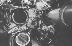

(source: uboataces.com)


(source: uboatarchive.net, visible tube, two guides for piston and piston itself)

The modification of the tube on U-995 looks like there was removed some inner
tube lining and added four guidndes - compare these photos (source: U-995.com)

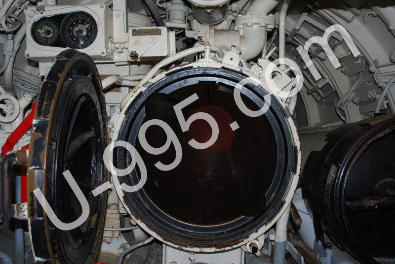

The torpedo in tube seems like G7a type, but it can be also some post-war type.
There is visible that torpedo is attached to these guidnes - so it can not be
original/combat fittnes and I would suggest not myself by this tube.

By the way - the piston that is placed near the aft torpedo tube on U-995 also looks like
not original one.

Quote from: NZSnowman
Also during your research have you come across any information about the oil lines? I am trying to find out what the tubing is made of. On the outer torpedo tube at Laboe Naval Memorial it show copper tubings, but I unsure if it is original.

According to U-231 and U-575 survivors interrogation report (http://www.uboatarchive.net/U-231INT.htm,
http://www.uboatarchive.net/U-575INT.htm) the tubes were initially made of bronze (and manganese -
see http://www.uboatarchive.net/U-257INT.htm).

But due to shortage of cooper in Germany later tubes were made of steel coated
with anti-corrosion preparation to prevent rusting. See:
U-257 survivors interrogation report - http://www.uboatarchive.net/U-257INT.htm
U-536 survivors interrogation report - http://www.uboatarchive.net/U-536INT.htm
U-172 survivors interrogation report - http://www.uboatarchive.net/U-172INT.htm
U-177 survivors interrogation report - http://www.uboatarchive.net/U-177INT.htm
U-1059 survivors interrogation report - http://www.uboatarchive.net/U-1059INT.htm

Looking at the dates of these reports, it seems that steel tubes were common practise sinse 1944,
but there are mentions, that they begin using steel year before.


--
Regards
Maciek

Offline SnakeDoc

  • Admiral
  • *
  • Posts: 536
  • Gender: Male
    • Torpedo Vorhaltrechner Project
Re: VIIC/41 - Schematices drawing
« Reply #746 on: 18 Dec , 2010, 13:42 »
I started a Wikipedia page today on U-1308. It in no way finish, will slowing keep updating it.

http://en.wikipedia.org/wiki/German_submarine_U-1308

Great idea, thanks for your work, Simon.

--
Regards
Maciek

Offline SnakeDoc

  • Admiral
  • *
  • Posts: 536
  • Gender: Male
    • Torpedo Vorhaltrechner Project
Re: VIIC/41 - Schematices drawing
« Reply #747 on: 18 Dec , 2010, 14:08 »
Hi Pat

Anyway, they look like they could be inlets for water speed but I'm still hesitant on that diagnosis.

Well, I don't know how to convince you.
HMS Graph British report on U-570 (http://uboatarchive.net/U-570BritishReport.htm) says it is pitometer type log.
ONI report on U-570  (http://uboatarchive.net/U-570ONIReport.htm) says the same.
Design study on IXC type (http://uboatarchive.net/DesignStudiesTypeIXC.htm) also.
http://u-historia.com/uhistoria/tecnico/articulos/corredera/corredera.htm
(you can use Google Translator)

Quote from: Pat
The same objections as before still apply, that in rough weather, they'd give false readings when the bow cam out of the water on high waves.  

Yes, that's right, the log could be not accurate on high seas. I think that german designers relized it.
This log type except above disadvantage also advantage - it is simpler and less fragile than  paddle-wheel one
(ie depth charges and running aground).

Quote from: Pat
Since then, I also wondered about their accuracy at different depths.  Since they'd have to work on pressure, the speed reading would differe depending on depth.  That doesn't seem workable.  A paddle-whell type knotmeter still makes more sense.

What?? Pitometer type log operating principle is differential pressure between dyniamic pressure
obtained from bow nozzles and static pressure obtainted from midship nozzles. That's why it is independent from depth.

Quote from: Pat
Also, while those are definitely there for a purpose, they don't seem to be standard since most pictures I've seen, there definitely isn't something like that in that location.

I think that the way how bow nozzles were installed was dependent from shipyard (similary as flooding holes) - sometimes
it was installed under the casing, covered by some grid, sometimes it was derived outside...

Did you see any paddle-wheel type log on german u-boats?

--
Regards
Maciek
« Last Edit: 18 Dec , 2010, 15:21 by SnakeDoc »

Offline NZSnowman

  • Admiral4
  • *
  • Posts: 2,419
  • Gender: Male
  • U-1308
    • U-1308 - Wikipedia
Re: VIIC/41 - Schematices drawing
« Reply #748 on: 18 Dec , 2010, 14:39 »
Quote from: Pat
Also, while those are definitely there for a purpose, they don't seem to be standard since most pictures I've seen, there definitely isn't something like that in that location.

I think that the way how bow nozzles were installed was dependent from shipyard (similary as flooding holes) - sometimes
it was installed under the casing, covered by some grid, sometimes it was derived outside...

--
Regards
Maciek

On this point I am starting to notic the nozzle on Type IX plans


From a Type IXC


From a Type IXC/40

Offline NZSnowman

  • Admiral4
  • *
  • Posts: 2,419
  • Gender: Male
  • U-1308
    • U-1308 - Wikipedia
Re: VIIC/41 - Schematices drawing
« Reply #749 on: 18 Dec , 2010, 14:45 »
Hi Maciek

Thanks again for your help!!!! I am glad that you also noticed the different inside of the tube, as I thought I was going crazy ;D

I will add this change to the U-995 list ;D

Simon


Offline SnakeDoc

  • Admiral
  • *
  • Posts: 536
  • Gender: Male
    • Torpedo Vorhaltrechner Project
Re: VIIC/41 - Schematices drawing
« Reply #751 on: 19 Dec , 2010, 03:23 »
Hello

I was wondering have you seen any information for either magnetic or gyro compass for the Gato? I been looking for information for the U-boat but not having much luck :(

Some time ago we have discussed magnetic projection compass installation.
I would like to supplement some informations (taken from "Submarine Design" by Urlich Gabler).
Quote
Until World War II, projection-type magnetic compasses were used as backup. These compasses were installed above the pressure hull in a nonmagneticzone with a spheric radius of about 1 m. Image transmission into the pressure hull was accomplished by lenses and prisms, and the image was projected onto a ground-glass plate. Submarine magnetic compasses cannot be adjusted accurately because of the interference caused by the heavy currents in the electrical networks and by the long pressure hull.

Back to the gyro-compasses - these ones used on german U-Boats were made by Anschutz, and were different than these used by Allies.
I do not have exact description of such compass, but from sources below you can find out how it looked and worked.

http://www.archive.org/details/anschutzgyrocom00ansciala - description of Anschutz systems used before WWII.

In Type IXC Design Study (http://uboatarchive.net/DesignStudiesTypeIXC.htm):
Quote
The gyro compass is of the Anschuetz bell type, which has been manufactured and installed commercially for many years.

Description of the gyro-compass from British Report on HMS Graph (http://uboatarchive.net/U-570BritishReport.htm)
Quote
   
            An Anschutz gyro-compass equipment of normal type is fitted.  The sensitive element is in the form of a sphere containing two gyros and a sealed damping trough.  The sphere is completely immersed in an acidulated water-glycerine mixture of suitable density to make it nearly but not quite buoyant, and it is supported inside the follow-up member by the repulsion effect of a coil inside the sphere carrying A-C current.  The 3-phase supply to the gyro rotors is taken through the liquid between conducting polar caps and an equatorial band.  Water is circulated from a tank through cooling coils in the compass bowl by means of a pump.  Follow-up is controlled by the difference of the liquid resistance path between two electrodes in the follow-up member and the edges of the centre band of the equatorial electrode on the sphere.  This difference controls a valve amplifier, the output of which drives a motor and transmitter.  The transmitter supplies a repeater motor on the compass drives the follow-up member.  Transmission is of the A-C type at 50 volts, 50 cycles, somewhat similar to Magslip or Selsyn, but the repeater motor makes one revolution per degree and is therefore comparable as regard torque with an "M" type motor.  In all A-C systems, however, the repeater load reacts on the transmitter and thus limits the maximum load which can be accepted.    
            The amplifier and control equipment in this installation has been fitted all in two boxes, thus reducing the overall sizes compared with ordinary Anschutz equipment.    
            A prism sight has been fitted at the window of the compass bowl to allow convenient observation of the sphere itself and a bracket close by to secure to steering gear, so that the ship can be steered by the compass, although the follow-up is not in operation.    
            A pressure resistant azimuth repeater is fitted on the bridge, and has a window about 4 in. diameter through which can be seen a cyclometer type dial giving the course in degrees, a circular dial giving 10
« Last Edit: 21 Dec , 2010, 07:48 by SnakeDoc »

Offline NZSnowman

  • Admiral4
  • *
  • Posts: 2,419
  • Gender: Male
  • U-1308
    • U-1308 - Wikipedia
Re: VIIC/41 - Schematices drawing
« Reply #752 on: 19 Dec , 2010, 11:43 »
Thanks again, Maciek.

I found this picture of the gyro on the net but I can not rememeber where.

« Last Edit: 21 Dec , 2010, 11:13 by NZSnowman »

Offline NZSnowman

  • Admiral4
  • *
  • Posts: 2,419
  • Gender: Male
  • U-1308
    • U-1308 - Wikipedia
Re: VIIC/41 - Schematices drawing
« Reply #753 on: 20 Dec , 2010, 22:36 »
Hi Maciek

Do you know how the aft torpedo tube is fixed to the pressure hull?

Simon

Offline SnakeDoc

  • Admiral
  • *
  • Posts: 536
  • Gender: Male
    • Torpedo Vorhaltrechner Project
Re: VIIC/41 - Schematices drawing
« Reply #754 on: 21 Dec , 2010, 00:57 »
Simon

Do you know how the aft torpedo tube is fixed to the pressure hull?

Maybe this helps...


source: u-995.com


source:  http://www.ubootwaffe.pl/component/option,com_flexicontent/Itemid,76/cid,66/id,337/view,items

--
Regards
Maciek

Offline NZSnowman

  • Admiral4
  • *
  • Posts: 2,419
  • Gender: Male
  • U-1308
    • U-1308 - Wikipedia
Re: VIIC/41 - Schematices drawing
« Reply #755 on: 21 Dec , 2010, 01:31 »
Thanks Maciek! It is the same way as the bow :)

Offline NZSnowman

  • Admiral4
  • *
  • Posts: 2,419
  • Gender: Male
  • U-1308
    • U-1308 - Wikipedia
Re: VIIC/41 - Schematices drawing
« Reply #756 on: 21 Dec , 2010, 01:57 »
Thanks Maciek! It is the same way as the bow :)

After a second look there a very small different on how the outer tube is bolted on to the pressure hull. I will hopley post drawings toworrow.

Offline Rokket

  • Administrator
  • *
  • Posts: 2,362
  • Gender: Male
  • Submarine Enthusiast
    • AMP - Accurate Model Parts
Re: VIIC/41 - Schematices drawing
« Reply #757 on: 21 Dec , 2010, 04:54 »
gryos (whether compass or guidance or science toy) are VERY cool, and they seemed to use them effectively in the 1930s. Very interesting stuff!
AMP - Accurate Model Parts - http://amp.rokket.biz

Offline NZSnowman

  • Admiral4
  • *
  • Posts: 2,419
  • Gender: Male
  • U-1308
    • U-1308 - Wikipedia
Re: VIIC/41 - Schematices drawing
« Reply #758 on: 21 Dec , 2010, 15:34 »
Hi Maciek

In Drawing 1 "Torpedo tube flooding and drainage installation" where is drain valve (i)? Is it the valve next (right) of the piston in Photo 3 "Aft torpedo tube on U-995"? 

Offline SnakeDoc

  • Admiral
  • *
  • Posts: 536
  • Gender: Male
    • Torpedo Vorhaltrechner Project
Re: VIIC/41 - Schematices drawing
« Reply #759 on: 22 Dec , 2010, 02:34 »
Simon

In Drawing 1 "Torpedo tube flooding and drainage installation" where is drain valve (i)? Is it the valve next (right) of the piston in Photo 3 "Aft torpedo tube on U-995"?  

Unfortunately, I cannot find any good, clear picture showing the drain valve of aft tube - it is covered by the piston.
The most clearer ist that:

(source: http://jaegers.net/index.php?id=53&L=1%27%60%28%5B%7B%5E%7E)

But if you look at the photo 16

you will see that arrangements is similar or even the same as for forward tubes, so the vavle must be
at the same place.

--
Regards
Maciek
« Last Edit: 22 Dec , 2010, 03:09 by SnakeDoc »

Offline NZSnowman

  • Admiral4
  • *
  • Posts: 2,419
  • Gender: Male
  • U-1308
    • U-1308 - Wikipedia
Re: VIIC/41 - Schematices drawing
« Reply #760 on: 22 Dec , 2010, 03:25 »
Thanks Maciek.

I am afraid there going to be lots more questions for you, as I have just started to drawing the piping to the tubes  ;D ;)

I was able to locate the drain valve (i) in Photo 4. Forward torpedo room on U-190  it is the 3-way valve under the cut-off valves (g) You can just made out the three pipes. You can see it also clearly in Photo 11. Forward torpedo room on U-995 (below)


Below is a close-up of the 3-way valve.


So this makes me believe this valve is on the starboard size of the aft tube, somewhere behind the open hatch door of Photo 3. Aft torpedo tube on U-995


Offline NZSnowman

  • Admiral4
  • *
  • Posts: 2,419
  • Gender: Male
  • U-1308
    • U-1308 - Wikipedia
Re: VIIC/41 - Schematices drawing
« Reply #761 on: 23 Dec , 2010, 10:37 »
Hi Pat

There a few stringer throughout the Type VII. I am trying to figure out if they run along the hull or span the full width of the hull. In general, do stringers run just next to the hull or do most usually span across the whole hull?

Simon

Offline Pat

  • Captain
  • *
  • Posts: 395
Re: VIIC/41 - Schematices drawing
« Reply #762 on: 28 Dec , 2010, 23:02 »
I'd have to know more information about this stringer.  Is this one on the pressure hull or just in the casing?

If it's in the PH, it would probably run the entire length of the boat.  As the purpose of a stringer is basically to keep the correct spacing of the ribs and add some strength, there'd be no point in putting it in unless it went the entire length.

However, if it's a stringer in the casing, then I'd have to know where in the casing you're talking about.  Because the casing of a U-boat is a sort of add-on, it's possible for the stringer to be only partial length.  It might stop when the side of the casing meets the PH, or it might go the whole length, or it might only be a partial strengthener for a limited section of the casing. 

I can see on the outside of the casing, a double line of rivets that look like they might be the attachment of a stringer running just under the free-flow holes both fore and aft, but it looks like it stops when it meets the saddle tank.  Is that where you're talking about?

Usually a stringer will be added inside the ribs, but it's possible in some constructs for it to be faired into the ribs, especially in a U-boat casing where the ribs are thicker than normal.

In surface ships, a stringer is also commonly a point where an interior deck attaches, in which case it depends on the deck locations whether it goes the length of the hull or not.  However, obviously that's not a consideration for a U-boat casing, since the only decks are inside the PH or the top of the casing.  However, it's possible for there to be a stringer inside the PH to be used for attaching the deck.

Offline NZSnowman

  • Admiral4
  • *
  • Posts: 2,419
  • Gender: Male
  • U-1308
    • U-1308 - Wikipedia
Re: VIIC/41 - Schematices drawing
« Reply #763 on: 30 Dec , 2010, 20:57 »
Hi Pat

Thanks for the information about the stringers. I was starting to get the additional information about the stringers for you when I noticed on plans they only run along the casting, so I answered my own question. I have found four stringers so far, two in the bow and other two in the stern. They range from approximately 1 to 4 m long. They are only single rivets (see below). Below is you can see the two stern stringers locations on U-995. Also from Westwood's you can see they only run along the side. Still trying to figaure out how they are fix to the casting.


Pictures from U-995 DVD http://www.uboataces.com/u995.shtml


Image from The Type VII U-Boat (Anatomy of the Ship)

Offline NZSnowman

  • Admiral4
  • *
  • Posts: 2,419
  • Gender: Male
  • U-1308
    • U-1308 - Wikipedia
Re: VIIC/41 - Schematices drawing
« Reply #764 on: 01 Jan , 2011, 13:14 »
Does anyone have any pictures of the bow plating? I am trying it get a view of the outlet valve at the bow.

Thanks, Simon.

Offline Rokket

  • Administrator
  • *
  • Posts: 2,362
  • Gender: Male
  • Submarine Enthusiast
    • AMP - Accurate Model Parts
Re: VIIC/41 - Schematices drawing
« Reply #765 on: 02 Jan , 2011, 01:22 »
awesome gyro! Sorry Simon, no pix
AMP - Accurate Model Parts - http://amp.rokket.biz

Offline NZSnowman

  • Admiral4
  • *
  • Posts: 2,419
  • Gender: Male
  • U-1308
    • U-1308 - Wikipedia
Re: VIIC/41 - Schematices drawing
« Reply #766 on: 03 Jan , 2011, 02:03 »
Evidence of evolution of the U-boat.

I started to redraw the bow section of my U-1308. I have been using the Fritz K

Offline Greif

  • Admiral2
  • *
  • Posts: 755
  • Gender: Male
Re: VIIC/41 - Schematices drawing
« Reply #767 on: 04 Jan , 2011, 23:54 »
Simon, I wish I had your drawing skills.  Beautiful as always!

Ernest

Offline SnakeDoc

  • Admiral
  • *
  • Posts: 536
  • Gender: Male
    • Torpedo Vorhaltrechner Project
Re: VIIC/41 - Schematices drawing
« Reply #768 on: 05 Jan , 2011, 15:24 »
Hi Simon

I am afraid there going to be lots more questions for you, as I have just started to drawing the piping to the tubes  ;D ;)

Go ahead, I'm still learning al lot - especially while researching the things, you asked about ;)

Your post made me wondering a lot.
Below there are things, I have been able to research for last few days.

Part One

Quote from: NZSnowman
In Drawing 1 "Torpedo tube flooding and drainage installation" where is drain valve (i)? Is it the valve next (right) of the piston in Photo 3 "Aft torpedo tube on U-995"?

Do you mean the valve marked with red arrow?

(source: http://www.ubootwaffe.pl/component/option,com_flexicontent/Itemid,76/cid,66/id,337/view,items)

I think that this is valve marked as (f) (look at the part related to aft tube) on the drawing:

(source: http://uboatarchive.net/U-570DesignBook.htm)

With blue arrow I have marked flood line, with green - vent/blow line and yellow - port part of torpedo compensating tank 1.


(source: http://uboatarchive.net/U-570DesignBook.htm)

Here is how I imagine myself this arrangement (sorry for hand drawing).


And one more view:

(source: U-995 DVD http://www.uboataces.com/u995.shtml)

red arrow - flood line
yellow arrow - branch to hull valve and cooling pump
green arrow - vent/blow line
blue arrow - valve (f)

I think that pipe part between red and blue arrows is blanked place after flow meter.


Part two

Quote from: NZSnowman
So this makes me believe this valve is on the starboard size of the aft tube, somewhere behind the open hatch door of Photo 3. Aft torpedo tube on U-995

Do you mean the valve marked with red arrow on the following photo?


I think that it can not be the drain valve because of two reasons:

If you look on the following photos you will see the the drain valve handle of the bottom tube in the same location
as for top tubes.


(source: http://www.ubootwaffe.pl/galeria/okrety/u-995/)


(courtesy of Britta Fischotter)

Also, drain valve located in place you pointed would make difficult to implement interlock between drain valve and opening doors gear.


I think that this is valve marked as (v) o the diagram


(source: http://uboatarchive.net/U-570DesignBook.htm)

This is valve used to select which torpedo compensating tank 2 or 3 is to be used to flood/drain the tubes.


--
Regards
Maciek

Offline SnakeDoc

  • Admiral
  • *
  • Posts: 536
  • Gender: Male
    • Torpedo Vorhaltrechner Project
Re: VIIC/41 - Schematices drawing
« Reply #769 on: 05 Jan , 2011, 16:22 »
After another while of wondering I think that arrangement for the aft tube is as follows:
(sorry for even worse hand drawing)


(source: U-995 DVD http://www.uboataces.com/u995.shtml)


(source: http://uboatarchive.net/U-570DesignBook.htm)


--
Regards
Maciek

Offline NZSnowman

  • Admiral4
  • *
  • Posts: 2,419
  • Gender: Male
  • U-1308
    • U-1308 - Wikipedia
Re: VIIC/41 - Schematices drawing
« Reply #770 on: 05 Jan , 2011, 16:55 »
Hi Maciek

Thanks for your time into this!

About part two

I also come to the same outcome as you about this valve only a few hours ago ;D I just could not get it to fix the plans, so I started looking in other places. Then I also notice the four drain valve handle. I will start drawing this up today and post within a few days.

From the picture below I have located the four opening in the bow casting for the drainage pipe (in Orange) however, they look a little small for the draining the tube. What do you think?

► Have you seen any measurement for the length of the torpedo tube within U-boat? I got a measurement of 3020 mm does this look right? It matches very near to the total length of 7552 mm.


From U-Boote Crews by J Delize


Here valve (v), I will join it up to the tank 2 or 3 later.

Offline NZSnowman

  • Admiral4
  • *
  • Posts: 2,419
  • Gender: Male
  • U-1308
    • U-1308 - Wikipedia
Re: VIIC/41 - Schematices drawing
« Reply #771 on: 06 Jan , 2011, 21:30 »
Hi Maciek

Here valve (i) including the interlocker. I was able to located two name plates but unable to make out that are on them :( The valve also a small bleed line (left) I try to follow it but was only able to follow it for about 40 cm it was heading to the Control panel (Ausgleicharmatur) in Photo 5.


Here the basic layout some far (will need to add the piping and things to get the right scale and postions). The blue pipe go back to tank 2. I could not location the orange drainage pipe on U-995 (maybe is has been removed :-\)

Offline NZSnowman

  • Admiral4
  • *
  • Posts: 2,419
  • Gender: Male
  • U-1308
    • U-1308 - Wikipedia
Re: VIIC/41 - Schematices drawing
« Reply #772 on: 06 Jan , 2011, 23:29 »
I wonder how this got on a German U-boat  ;D ;)


Norwegian  ;D ;D - Look like they miss this name plate.

Offline SnakeDoc

  • Admiral
  • *
  • Posts: 536
  • Gender: Male
    • Torpedo Vorhaltrechner Project
Re: VIIC/41 - Schematices drawing
« Reply #773 on: 07 Jan , 2011, 02:41 »
Hi Simon

Have you seen any measurement for the length of the torpedo tube within U-boat? I got a measurement of 3020 mm does this look right? It matches very near to the total length of 7552 mm.

Unfortunately I have never met exact measurement of the part of the tube inside and outside the boat.
I suppose, that for that moment you have to estimate it from the drawings.

--
Regards
Maciek

Offline SnakeDoc

  • Admiral
  • *
  • Posts: 536
  • Gender: Male
    • Torpedo Vorhaltrechner Project
Re: VIIC/41 - Schematices drawing
« Reply #774 on: 07 Jan , 2011, 02:50 »
From the picture below I have located the four opening in the bow casting for the drainage pipe (in Orange) however, they look a little small for the draining the tube. What do you think?

I think that it has to be opening for the drain pipe - in my opinion this is the only possibilty.

You can compare the size of the pipe in US Navy tubes - it isn't much different:
http://maritime.org/fleetsub/tubes/plate1.htm

Although I must admit that there is one hole too many for each tube - I'm trying to figure it out.

--
Regards
Maciek

Offline SnakeDoc

  • Admiral
  • *
  • Posts: 536
  • Gender: Male
    • Torpedo Vorhaltrechner Project
Re: VIIC/41 - Schematices drawing
« Reply #775 on: 07 Jan , 2011, 03:02 »
Meantime I figure out one more part of installation:


(source: http://www.ubootwaffe.pl/galeria/okrety/u-995/)

blue arrow - hull valve (a)

compare valve handle with:

(source: http://www.uboatarchive.net)

yellow arrow - valve (h)
green arrow - connection to equalizing pressure
red arrow - connection to compensating tanks


(source: http://www.uboatarchive.net)

--
Regards
Maciek

Offline SnakeDoc

  • Admiral
  • *
  • Posts: 536
  • Gender: Male
    • Torpedo Vorhaltrechner Project
Re: VIIC/41 - Schematices drawing
« Reply #776 on: 07 Jan , 2011, 04:22 »
Here valve (i) including the interlocker. I was able to located two name plates but unable to make out that are on them :( The valve also a small bleed line (left) I try to follow it but was only able to follow it for about 40 cm it was heading to the Control panel (Ausgleicharmatur) in Photo 5.


Great work Simon!
Here is another view of the drain valve:

(source: http://www.ubootwaffe.pl/galeria/okrety/u-995/)

I cannot figure out at this moment what this small bleed line is for.

Quote from: NZSnowman

Here the basic layout some far (will need to add the piping and things to get the right scale and postions). The blue pipe go back to tank 2. I could not location the orange drainage pipe on U-995 (maybe is has been removed :-\)

I think, that drainage line for the top tubes are hard to see because they are between the tubes and hull, as well you cannot locate the lines for bottom, because they are under the deck.


This is forwardo torpedo room of U-164 - type IXC boat, but arrangement seems the same.

(source: Vom Original zum Modell, Uboottyp IX C)

blue arrow - opening for the shaft of the muzzle door opening gear
green arrow - compressed air pipe for the mine bolt actuator
orange arrow - drainage pipe
yellow arrow - vent/blow pipe
red arrow - compressed air line for ejecting mines
white arrow - compressed air line for ejecting mines

I have doubts about two last openings - according to drawing below, there should be only one...
I'm gonna investigate it thorough...


(source: http://www.uboatarchive.net)

--
Regards
Maciek
« Last Edit: 07 Jan , 2011, 16:25 by SnakeDoc »

Offline dougie47

  • Administrator
  • *
  • Posts: 758
Re: VIIC/41 - Schematices drawing
« Reply #777 on: 07 Jan , 2011, 09:17 »
Hi Simon,

A few weeks back you requested a photo showing how the aerial met with the aft deck. This should help -

http://cgi.ebay.com/ORIG-PHOTO-U-BOOT-U-BOAT-U-212-CREWMEN-W-FLAG-DECK-/110630725459?pt=LH_DefaultDomain_0&hash=item19c21ae753

Cheers,

Dougie

Offline NZSnowman

  • Admiral4
  • *
  • Posts: 2,419
  • Gender: Male
  • U-1308
    • U-1308 - Wikipedia
Re: VIIC/41 - Schematices drawing
« Reply #778 on: 07 Jan , 2011, 11:38 »
Hi Simon,

A few weeks back you requested a photo showing how the aerial met with the aft deck. This should help -

http://cgi.ebay.com/ORIG-PHOTO-U-BOOT-U-BOAT-U-212-CREWMEN-W-FLAG-DECK-/110630725459?pt=LH_DefaultDomain_0&hash=item19c21ae753

Cheers,

Dougie

Thanks Dougie!!! The picture is wonderful. It nice and clear!

Dougie, when you look at the small section between the deck and wire block, does it look like solid metal or metal wire?

Offline NZSnowman

  • Admiral4
  • *
  • Posts: 2,419
  • Gender: Male
  • U-1308
    • U-1308 - Wikipedia
Re: VIIC/41 - Schematices drawing
« Reply #779 on: 07 Jan , 2011, 12:17 »
Meantime I figure out one more part of installation:


(source: http://www.ubootwaffe.pl/galeria/okrety/u-995/)

blue arrow - hull valve (a)

compare valve handle with:

(source: http://www.uboatarchive.net)

yellow arrow - valve (h)
green arrow - connection to equalizing pressure
red arrow - connection to compensating tanks


(source: http://www.uboatarchive.net)

--
Regards
Maciek

Great work!!!

To my understanding the inlet is only on the port side of the boat, is that right Maciek ???

I have some original German measurement for this inlet for the pressure hull. I will measure this out on the outside of the boat and see how it matches on the inside.

Maciek, have you seen the information that Dani from http://www.u-historia.com/ got from Joachim Scherneck-Czech, Archives assistant in Military historical training centre of the naval college M

Offline NZSnowman

  • Admiral4
  • *
  • Posts: 2,419
  • Gender: Male
  • U-1308
    • U-1308 - Wikipedia
Re: VIIC/41 - Schematices drawing
« Reply #780 on: 07 Jan , 2011, 12:35 »
Hi Simon

Have you seen any measurement for the length of the torpedo tube within U-boat? I got a measurement of 3020 mm does this look right? It matches very near to the total length of 7552 mm.

Unfortunately I have never met exact measurement of the part of the tube inside and outside the boat.
I suppose, that for that moment you have to estimate it from the drawings.

--
Regards
Maciek

Thanks, the measurement of 3020 mm will be either one of the following

Offline NZSnowman

  • Admiral4
  • *
  • Posts: 2,419
  • Gender: Male
  • U-1308
    • U-1308 - Wikipedia
Re: VIIC/41 - Schematices drawing
« Reply #781 on: 07 Jan , 2011, 12:47 »
Maciek, I read that the late war Type VIIC/41 lost the function of using mines. If, so that would happened to say the opening in the bow cap casting for the compressed air pipe for the mine bolt actuator? Would they just wield up the opening or do you think they redesign the bow cap for the Type VIIC/41 ???

Offline dougie47

  • Administrator
  • *
  • Posts: 758
Re: VIIC/41 - Schematices drawing
« Reply #782 on: 07 Jan , 2011, 13:00 »
Hi Simon,

Thought you would like the image :)

I reckon there is a piece on the deck that might be triangular (or something like a triangle). The block at the end of the jumping wire connects around this triangular piece, with either a rivet or a nut/bolt holding the block onto the triangle.  That's what it looks to me.

Cheers,

Dougie

Offline NZSnowman

  • Admiral4
  • *
  • Posts: 2,419
  • Gender: Male
  • U-1308
    • U-1308 - Wikipedia
Re: VIIC/41 - Schematices drawing
« Reply #783 on: 07 Jan , 2011, 13:27 »
Hi Dougie

I am easy to please ;D

I think a triangular make 100% more sense than my idea! I will check my drawing and see of there any framing under the deck in the vicinity of the fix point.

Two things I just notice, one a white strip across the deck - training boat?

And a wield line near the stern of the casting, I have not see this before, will need to check this.

Offline SnakeDoc

  • Admiral
  • *
  • Posts: 536
  • Gender: Male
    • Torpedo Vorhaltrechner Project
Re: VIIC/41 - Schematices drawing
« Reply #784 on: 07 Jan , 2011, 16:21 »
Hi Simon

To my understanding the inlet is only on the port side of the boat, is that right Maciek ???

That's right.

I have some original German measurement for this inlet for the pressure hull. I will
measure this out on the outside of the boat and see how it matches on the inside.

Where have you got this measurement?
Is it from the link you gave below, or some else source?
Please give the info, if this match.

Maciek, have you seen the information that Dani from http://www.u-historia.com/ got from Joachim Scherneck-Czech,
Archives assistant in Military historical training centre of the naval college M

Offline SnakeDoc

  • Admiral
  • *
  • Posts: 536
  • Gender: Male
    • Torpedo Vorhaltrechner Project
Re: VIIC/41 - Schematices drawing
« Reply #785 on: 07 Jan , 2011, 16:25 »
Maciek, I read that the late war Type VIIC/41 lost the function of using mines. If, so that would happened to say the opening in the bow cap casting for the compressed air pipe for the mine bolt actuator? Would they just wield up the opening or do you think they redesign the bow cap for the Type VIIC/41 ???

Yes, I think, that they would only weld up the openings for the compressed air pipe
for mine bolt actuator as well as for mine discharge lines.
I don't think that redesigning the bow was necessery.

--
Regards
Maciek

Offline NZSnowman

  • Admiral4
  • *
  • Posts: 2,419
  • Gender: Male
  • U-1308
    • U-1308 - Wikipedia
Re: VIIC/41 - Schematices drawing
« Reply #786 on: 07 Jan , 2011, 21:51 »

I have some original German measurement for this inlet for the pressure hull. I will
measure this out on the outside of the boat and see how it matches on the inside.

Where have you got this measurement?
Is it from the link you gave below, or some else source?
Please give the info, if this match.

The original German measurements are from the Fritz K

Offline NZSnowman

  • Admiral4
  • *
  • Posts: 2,419
  • Gender: Male
  • U-1308
    • U-1308 - Wikipedia
Re: VIIC/41 - Schematices drawing
« Reply #787 on: 08 Jan , 2011, 12:59 »
Here I have got next few parts of flood installation.

For the port side:


(source: http://www.ubootwaffe.pl/galeria/okrety/u-995/)


(source: http://uboatarchive.net/U-570Plate7.htm)

For the starboard side:


(source: U-995 DVD http://www.uboataces.com/u995.shtml)


(source: http://uboatarchive.net/U-570Plate7.htm)

I think that blue arrow points the blank place, where the flow meter was installed.


--
Regards
Maciek

Hi Maciek

Would not the Black Arrow be the flow meter? It found on both side, and its look like the lid flip open to display a counter at the top.

Also how good is your German (or anyone) I just can not like out all the letters on this name plate. Also below the name plate you can see a flow arrow which you usually always found a flow meters.

Offline SnakeDoc

  • Admiral
  • *
  • Posts: 536
  • Gender: Male
    • Torpedo Vorhaltrechner Project
Re: VIIC/41 - Schematices drawing
« Reply #788 on: 08 Jan , 2011, 13:25 »
Hi Simon


Would not the Black Arrow be the flow meter? It found on both side, and its look like the lid flip open to display a counter at the top.

Also how good is your German (or anyone) I just can not like out all the letters on this name plate. Also below the name plate you can see a flow arrow which you usually always found a flow meters.


Great photo.
It is clearly visible, the plate says:
Flutv Z

Offline NZSnowman

  • Admiral4
  • *
  • Posts: 2,419
  • Gender: Male
  • U-1308
    • U-1308 - Wikipedia
Re: VIIC/41 - Schematices drawing
« Reply #789 on: 09 Jan , 2011, 12:13 »
Hi Maciek

► Do you have any views of the piping (Red Arrow) to the left of this photograph? I am trying to follow the pipe out of the flow meter.

► Also from below, the valve to the sea: Originally I was thinking this was only an inlet valve, but now I think it an inlet and out valve, is this correct?


► I think I have located the two main drain valves (f) from the drainage system.


Plate 6:  Trimming, compensating and drainage system

Offline SnakeDoc

  • Admiral
  • *
  • Posts: 536
  • Gender: Male
    • Torpedo Vorhaltrechner Project
Re: VIIC/41 - Schematices drawing
« Reply #790 on: 09 Jan , 2011, 15:13 »
Hi Simon

► Do you have any views of the piping (Red Arrow) to the left of this photograph? I am trying to follow the pipe out of the flow meter.

Unfortunately I do not have any views, moreover, viewing below pictures, I think that this piping is led under the deck/casing and it is hard to see.


(source: http://www.ubootwaffe.pl/galeria/okrety/u-995/)

► Also from below, the valve to the sea: Originally I was thinking this was only an inlet valve, but now I think it an inlet and out valve, is this correct?

Yes, the valve can take water from the sea as well as can be used to blow water from compensating tanks.

I think I have located the two main drain valves (f) from the drainage system.

I'm sure you identified the valves correctly.

Where does this photo come from?
Is this from uboataces.com U-995 DVD?


--
Regards
Maciek

Offline NZSnowman

  • Admiral4
  • *
  • Posts: 2,419
  • Gender: Male
  • U-1308
    • U-1308 - Wikipedia
Re: VIIC/41 - Schematices drawing
« Reply #791 on: 09 Jan , 2011, 16:00 »
Unfortunately I do not have any views, moreover, viewing below pictures, I think that this piping is led under the deck/casing and it is hard to see.

I am sure I have located the two pipes I am looking for from photographs. One is directly under the personal lockers and another pipe runs along the pressure hull near the floor. I am sure I know with pipe belong to which system, base on the size of the pipes, but I was hoping to double check this.

Where does this photo come from?
Is this from uboataces.com U-995 DVD?

They are from a member of the SubSim Forum. You have PM.

Offline NZSnowman

  • Admiral4
  • *
  • Posts: 2,419
  • Gender: Male
  • U-1308
    • U-1308 - Wikipedia
Re: VIIC/41 - Schematices drawing
« Reply #792 on: 09 Jan , 2011, 21:34 »
Inlet/outlet valve with flow meter including piping


Offline SnakeDoc

  • Admiral
  • *
  • Posts: 536
  • Gender: Male
    • Torpedo Vorhaltrechner Project
Re: VIIC/41 - Schematices drawing
« Reply #793 on: 10 Jan , 2011, 02:11 »
I am sure I have located the two pipes I am looking for from photographs. One is directly under the personal lockers and another pipe runs along the pressure hull near the floor. I am sure I know with pipe belong to which system, base on the size of the pipes, but I was hoping to double check this.

Well, in such case I can't wait to see the drawings :)

--
Regards
Maciek

Offline SnakeDoc

  • Admiral
  • *
  • Posts: 536
  • Gender: Male
    • Torpedo Vorhaltrechner Project
Re: VIIC/41 - Schematices drawing
« Reply #794 on: 10 Jan , 2011, 02:13 »
Inlet/outlet valve with flow meter including piping

As usuall great work Simon! :)

--
Regards
Maciek

Offline SnakeDoc

  • Admiral
  • *
  • Posts: 536
  • Gender: Male
    • Torpedo Vorhaltrechner Project
Re: VIIC/41 - Schematices drawing
« Reply #795 on: 10 Jan , 2011, 02:16 »
Simon

I have got request - could you give me the distance of the
mine stop bolt (marked with red arrow) to the rear and fore end of torpedo tube?


--
Regads
Maciek

Offline NZSnowman

  • Admiral4
  • *
  • Posts: 2,419
  • Gender: Male
  • U-1308
    • U-1308 - Wikipedia
Re: VIIC/41 - Schematices drawing
« Reply #796 on: 10 Jan , 2011, 08:39 »

Offline SnakeDoc

  • Admiral
  • *
  • Posts: 536
  • Gender: Male
    • Torpedo Vorhaltrechner Project
Re: VIIC/41 - Schematices drawing
« Reply #797 on: 10 Jan , 2011, 09:02 »


Thank you very much, Simon ;)

--
Regads
Maciek

Offline SnakeDoc

  • Admiral
  • *
  • Posts: 536
  • Gender: Male
    • Torpedo Vorhaltrechner Project
Re: VIIC/41 - Schematices drawing
« Reply #798 on: 13 Jan , 2011, 06:10 »
Hi Simon


► Also from below, the valve to the sea: Originally I was thinking this was only an inlet valve, but now I think it an inlet and out valve, is this correct?


Yes, the valve can take water from the sea as well as can be used to blow water from compensating tanks.


I have been thinking about this hull valve, and although there are no objections
towards 'bidirectional' valve (no stop- or check-valve), now I guess, that it was used as
intake only.

I am convinced, that pipe line leading to the compensating tank is installed as you
have drawn on below drawing - it ends at the top of the tank).


If so - the tank can not be empted by pressured air, and water can not be blown through the hull valve.
To accomplish it, the pipe should be led to the bottom of the tank (as the blue pipe
leading to the torpedo tube.

So the tanks had to be emptedy by means of drainage installation and main drain or auxilary drain/trimming pumps.

--
Regards
Maciek

Offline NZSnowman

  • Admiral4
  • *
  • Posts: 2,419
  • Gender: Male
  • U-1308
    • U-1308 - Wikipedia
Re: VIIC/41 - Schematices drawing
« Reply #799 on: 13 Jan , 2011, 21:19 »
Hi Maciek

I think you are right. If you look at Plate 11:  High pressure air system & Plate 12:  Low pressure or service air system there no air lines going to Compensating Tank 2 & 3. The only a air line is to the Forward Trim Tank (this is the air line you can see in P1100408.JPG :-\) On Plate 6:  Trimming, compensating and drainage system you can see the piping to drain Compensatings Tank 2 & 3.

I need to update the blue pipe, as I think I have make the diameter to big (I have it at 70 mm now but I starting to think it more like 60 mm) and I am almost certain it does not go through the Forward Trim Tank but long the top like is the picture (P1100408.JPG). I also need to add it to both starboard and port side of the boat.