Recent Posts

Pages: [1] 2 3 ... 10
1
General Model Discussion / Chicago's Riverview - Pair-O-Chutes Tower
« Last post by NemVia on 08 Oct , 2024, 16:09 »
[size=var(--font-size-display-medium)][/color][color=var(--color-text)][/color][/size][size=var(--font-size-medium)]I've spent most of my life building various kit models from boats to race cars to funny cars and dragsters and even Starships. Building some of these models from scratch has been an enjoyable experience for me because I can custom make all of the parts for the project. For years I've wanted to start this next project, but the lack of information and photos and building materials was the big factor in delaying the start. Since the internet has come into existence, many more people have been willing to upload their personal photos and home movies to allow many different people to enjoy what they once experienced. The types of building materials have also changed and are more accessible to the lowly hobbyist, like me, in local hobby shops or buying direct from certain manufacturers directly on-line. This time, though I wanted to build something that was special to me. It was something that many Chicagoans knew of up until 1967 when it was removed altogether from existence. I was never old enough to ride it, but I could see it right from my bedroom window day or night. It was just one of those things I will always remember in my mind and heart. I am of course speaking of Riverview's Pair-O-Chutes ride. A six-parachute freefall ride from atop a 210-foot tower. Something that many modern B.A.S.E jumpers could have gone on legally and with complete safety.[/size][size=var(--font-size-medium)]But this ride was not always the Pair-O-Chute jump that many remember.[/size][size=var(--font-size-medium)]In 1910 the ride opened up as the "Eye-Full" tower. A tongue in cheek name adapted from of course the Eifel Tower in Paris France. Its function was that of an observation tower in which individuals could be lifted up the center of the tower via a pneumatic elevator system to a glass enclosed 360-degree viewing platform of the city hence the name "EYE-FULL". What a shame it is that no one thought to bring one of the early cameras up there to take some awesome pictures of the surrounding area. As it turns out though, the city of Chicago felt that pneumatic elevator system was entirely unsafe and so the ride was shut down until a safer elevator system could be installed. Later a more traditional cable and counterweight system was installed, and the attraction was reopened. The tower remained open for a few more years and was then closed down once again and it stood until it was decided to add the spans on the tower and make the first free-fall parachute ride at an amusement park. [/size][size=var(--font-size-medium)]


Same tower, different function. I was 4 years old when they tore the park down and I remember how just that summer before my mom promised me when I was old enough, I could go on that ride as many times as I wanted. Of course that could never be. But I never stopped thinking about the ride. As I got older, I began building models from cardboard and other materials. I began to build some of them solely from drawings and blueprints. I knew that one day I would find the materials I needed to build a replica of this tower. I found pictures of all kinds on the internet including a model of the Pair-O-Chutes that was built by a former employee of Riverview out of brass. I have to say, I can't stand working with brass, but he did give me the push I needed to start doing research on my own build. At first many of the pictures I found of the tower were not detailed enough for me to figure out how it was constructed. This was the case until I met another former employee of the park who actually operated and maintained the ride. I took a chance and wrote to him, and he did respond about a month later. He sent me some higher resolution copies of photos that he actually took while on the tower. Views that I had never seen before that revealed that the tower was basically made from steel angle-iron and steel rods. I found some professionally made documentaries from news reels online and saw even more of what I needed to finally begin my project.
But what do I build it out of, and how large would it be? I knew that some hobby shops had copper piping and steel rods and even brass stock for building certain items. But what I didn't find was any angle-iron or angle shaped metals. I suddenly remembered there was another perfect source of materials in plastics. Evergreen Styrene products was the way to go. They had all different sizes and shapes of what I needed to at least start building prototype pieces. At first, I wanted to build a tower at 1" = 1' which would have made the tower over 17' tall. I really didn't have the room for that even in our yard. So, I whittled it down to a 6-foot model.


So, the first "Icon" I am building will be the "EYE-FULL" part of the tower. There was a lot of guess work in the slope of the outside part of the legs. The final product was achieved by building the inside part of the leg and then taping it to a support pole I have in my basement. Then I built the outside part of the leg and taped the two ends at the top together, then I mounted a cut-out of the tower on a mic-stand and placed it at a distance to where I could view it with one eye and the built parts of the leg with my other eye. I taped the bottom of the outside leg to a book and kept moving the book away from the base of the other leg until it appeared to match what I was seeing with my other eye on the picture. I literally eye-balled the leg to build it as close to the original as possible. Next, I measured off 17 tiers on the inner leg including the very top of the tower leg. I took a small level and held it at each of the marks on the leg and measured off each of the widths up to tier 13.


I needed to build 12 of these support legs. So, I took an old piece of drywall, a 6' piece of aluminum c-channel and a bunch of clamps and pushpins and I drew a template on the drywall so that all of the legs would be built exactly the same height and width. Next, I needed to find out the distance that the tower's interior parts of the legs would be from each other, so I taped two of the legs to my basement wall and used my cut out of the tower again to figure what the space was. Each leg was 11" apart from its immediate opposite. In order to build this tower as circular as possible I bought a 10" concrete form; I measured on the outside of the form 12 segments from top to bottom around the entire tube and then I cut 12 - 1/2" strips to make up the 11" and taped all 12 strips to the outside of the tube. Next, I taped all of the legs in place to make sure they would stay centered as I began adding all of the bracing rods starting from the inside leg and working outward.


 Here you can see the inside led cross bracing in place. I also had to add 2 more inches to the bottom of the tower legs because I found a very rare arial photo of the tower that shows the bracing on the lowest tier. To make it easier to paint all of these intricate parts I first painted all of the legs one at a time. Next, I sprayed all of the bracing rods except for the ends so that I can cement everything in place.


I've also started the horizontal cross-bracing. After I get this finished, I will add more horizontal rods to the outer parts of the legs and then I can touch up the exposed white parts of the bracing rods. A pretty cool note: Before I added the horizontal bracing, the outer parts of the legs would wobble when I would lightly bump them, but now that they have this bracing in place the legs are very sturdy. I was a bit worried about the strength of the structure because eventually I will have to remove the concrete form and the wood strips so the structure will be free-standing and sturdy. My fears have now abated. I do have to order more rods for the bracing, but after the entire tower is done, I can begin to build the second Icon which will be the PAIR-O-Chutes arms. Please feel free to ask any questions about the build and if there's any additional details you think I could add, please let me know as well. Thanks for reading! See you next update for part 2.
(End of part 1)[/size]
2
SUBS: other / Re: SLC "maiale" 1/400 scale WIP
« Last post by SG on 13 Sep , 2024, 07:21 »
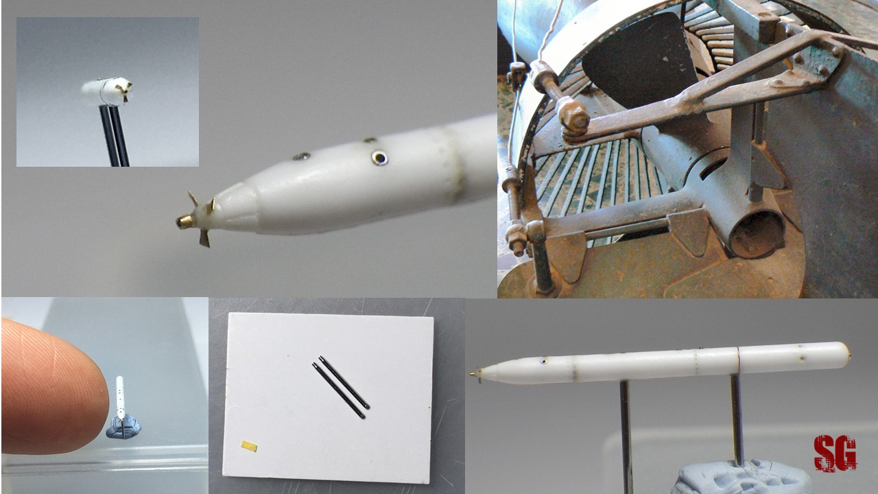
Propeller blades are ready. Crafted from 0.05 mm brass shim, some 0.4-ish mm long.


https://u.cubeupload.com/SGm/propellerblades.jpg


Cheers,


SG
3
TYPE IX / 1/72 U-525 kit for sale (Tehnoart)
« Last post by U-525 on 15 May , 2024, 09:04 »
I have the rarest U-Boat model ever (one of one). It's the Tehnoart U-525 (my new username, formerly snegron). It's a mixed media kit, 3D printed everything, TONS of PE and cast brass, MUCH higher in quality than the Revell U-190 (and differences based on it being U-525, different schnorkel and many other differences). They sold them pre-built and painted but I got them to send me a kit, along with U-505 as they were selling 11 of them as unbuilt kits. For years I was "the only kid on my block" with a 1/72 Type IX (LOL)! I paid $650 for U-525 many years ago and wish to sell it. If you're interested, PM me or email me at scottnegron@comcast.net. I can send pictures of the parts, and the instructions (once I find a CDROM to copy them as that's where the instructions are and CDROM players are like VCRs now)!


Thanks:)!


Scott
4
TYPE IX / U-505 (etc.) railing dimensions
« Last post by U-525 on 15 May , 2024, 08:53 »
I'm working with Sasa Distephano to revise his U-Boat railings line and we're looking for accurate dimensions. Years ago, a curator at the museum measured them for me, but I can't find them, he's deceased, and I haven't heard back from the museum. I've seen .6 to .7mm (thicker ones), and .4mm for the thinner ones. As this will be for a "premium" edition we'd like to get them right. Any help greatly appreciated!  Scott
5
TYPE IX / Re: U-505 Markings
« Last post by U-525 on 15 May , 2024, 08:49 »
I don't have any extras, but my late friend Keith Davidson (Red Pegasus Decals) drew and printed me outstanding one's taken from a photo of U-505 at the museum. They have a lot of detail in the shell and variations on the background (a greenish black, a little uneven to give it that "hand painted" look). I can send you an image, maybe you can see if you can have someone with an Alps printer make you copies. Good luck!
6
SUBS: other / Re: SLC "maiale" 1/400 scale WIP
« Last post by SG on 15 Apr , 2024, 12:13 »

Hi,
a small update. The instrument cluster and the controls for the trim pumps with their knobbed levers are finally ready after two months of hard work. 0.2 brass tubing for the cylindrical parts, 0.046 mm wire for levers and frame. Instrument cluster: depth gauge and compass = very thin sections of 0.2 mm brass wire and tubing. 0,1 "dots" of alu foil for the gauges on the right (ammeters and voltmeters). Enjoy


Cheers,

SG


PS: the blog's updated  ( https://3xblackcats.wordpress.com/side-projects/ )
7
ALL other U-boats / Re: Robbe`s type XXI, 1/40, U-2511.
« Last post by Bad Karma on 17 Mar , 2024, 10:44 »
Not much to report, decided to remove the paint job from the flat-bed with nail polish remover. I was not happy, it irritated me.
Some parts broke off, i was allreay aware of that would happen.
Also working on the new tech-rack for the U-47, there is little malfunction in the electronics.
The servos are nervous, in the neutral state. More on that later.

Paint job almost removed.
 

Vallejo wheaterings set.


And these models for a future project are on my most wanted list, a littlebit expensive. I have to think about it.


Regards,

Ron.
8
TYPE IX / Re: Sunken U-Boat
« Last post by tankerken on 12 Feb , 2024, 16:59 »
Another View of the shark.
Ken
9
TYPE IX / Re: Sunken U-Boat
« Last post by SG on 12 Feb , 2024, 09:09 »
Lovely build! I like the shark idea  8)
10
TYPE IX / Re: Sunken U-Boat
« Last post by tankerken on 11 Feb , 2024, 21:33 »
Blast damage.
Ken
Pages: [1] 2 3 ... 10