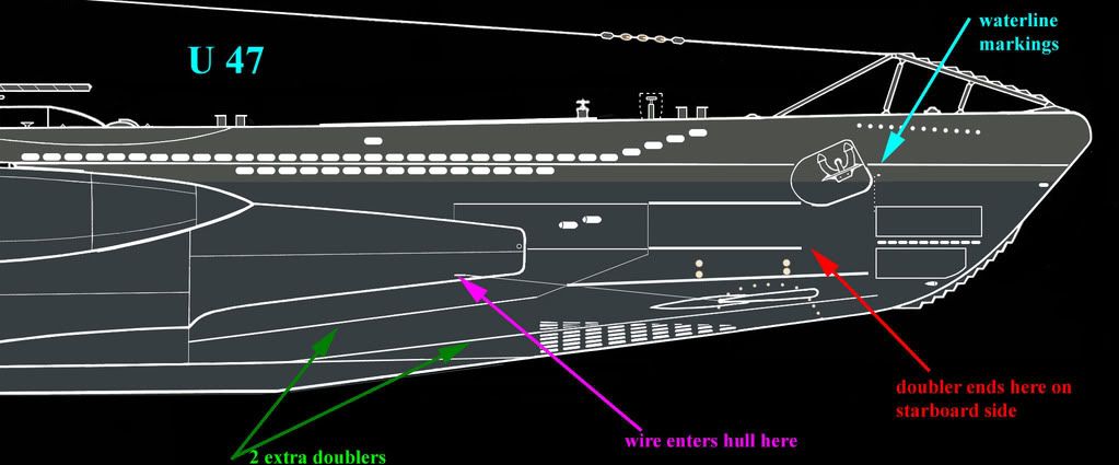
Before I forget, have you added the 2 doublers (the strengthening strips) that were located behind the forward planes? The green arrow points to them. Neither of the doublers are on the Revell kit. I'm not sure these 2 doublers were quite as wide as the other doublers on the hull casing but it is hard to be sure. You can also see them on page 25 and page 27 of Steve Wiper's pictorial book.
Cheers,
Dougie
I have a question about the lower doubler as shown in your pic.
The lower doubler starts near the bottom of the casing (just above the keel) and goes fowards and upwards.
But where does it end?
a) ends in line with the upper doubler
b) ends at the rear edge of the lower flooding vents
c) continues all the way forward to below the lower torpedo door
I noticed that in the Modelbrass PE lower flooding vents, there are the top 3 rows of vents... then a wide gap... then the remaining 5 rows of vents.

From your line drawing, if the lower doubler went all the way forward, it looks like it would pass through that wide gap in the lower flooding vents and continue forward.
However, where your line drawing shows the end of that doubler ending below the lower torpedo door, on the model it would end up at the bow plane pivot hole. Maybe it's an error in the PE vents, but to make the doubler pass through that wide gap in the PE vents... the angle makes it end in the wrong place.
Hopefully this last part makes sense... if not then I'll take a pic of my model with the proposed path of the doubler drawn on it.

