Author Topic: VIIC/41 - Schematices drawing  (Read 589080 times)

0 Members and 32 Guests are viewing this topic.

Offline SG

  • Admiral
  • *
  • Posts: 661
    • https://3xblackcats.wordpress.com/
Re: VIIC/41 - Schematices drawing
« Reply #1000 on: 07 Dec , 2011, 07:47 »
Hey Simon!
Check your personal message inbox here at AMPforum, I've sent you some pictures and artworks which might help..
keep up the stunning-classy work!
SG

Offline Pepper-mint

  • Commander
  • *
  • Posts: 343
  • Gender: Male
  • U-1299
Re: VIIC/41 - Schematices drawing
« Reply #1001 on: 14 Dec , 2011, 04:23 »
Simon,

This is your 1000 and ONE reply...

For the flakvierling plans, i'll check as soon as i'm back to Leb...

heers mate  ;)
Pepper
On the W.bench :
Books, pics, drawings, styrene, dreams and :

Offline NZSnowman

  • Admiral4
  • *
  • Posts: 2,419
  • Gender: Male
  • U-1308
    • U-1308 - Wikipedia
Re: VIIC/41 - Schematices drawing
« Reply #1002 on: 22 Dec , 2011, 01:34 »
The dockworkers and crew of U-1308, which like to wish anyone a Marry Christmas and a Happy New Year.

Offline Rokket

  • Administrator
  • *
  • Posts: 2,362
  • Gender: Male
  • Submarine Enthusiast
    • AMP - Accurate Model Parts
Re: VIIC/41 - Schematices drawing
« Reply #1003 on: 23 Dec , 2011, 03:28 »
Thanks mate! and you too! Hope the new Christchurch quakes haven't affected you.
AMP - Accurate Model Parts - http://amp.rokket.biz

Offline NZSnowman

  • Admiral4
  • *
  • Posts: 2,419
  • Gender: Male
  • U-1308
    • U-1308 - Wikipedia
Re: VIIC/41 - Schematices drawing
« Reply #1004 on: 23 Dec , 2011, 11:31 »
Thanks mate! and you too! Hope the new Christchurch quakes haven't affected you.

All this well! Yes, it has been a Rock & roll time for Christchurch within that last 24 hours.

5 large earthquakes within 2 hours. The first was 5.8 and hit at 1.58pm yesterday, followed by a 5.3 quake at 2.06pm. At 2.14pm there was a 4.2 magnitude one but the largest was 6.0 and struck at 3.18pm. It was followed by a 5.0 magnitude jolt at 3.50pm.

Since 4:00pm yesterday they have recorded 21 earthquakes between 3.2 and 5.1 magnitude.

Off to Christchurch today for Christmas with the family.

Offline Rokket

  • Administrator
  • *
  • Posts: 2,362
  • Gender: Male
  • Submarine Enthusiast
    • AMP - Accurate Model Parts
Re: VIIC/41 - Schematices drawing
« Reply #1005 on: 23 Dec , 2011, 23:51 »
Wow. Good luck!

We had a tiny one in Adelaide a few months ago, in the middle of the night, wounded like a freight train or giant dumpster banging, house rumbled, shelves vibrated, woke us right up! Pretty scary, it just goes and you can't do anything!

Enjoy Christmas! (and have a nice break form your intense and awesome drawing!)

AMP - Accurate Model Parts - http://amp.rokket.biz

Offline Greif

  • Admiral2
  • *
  • Posts: 755
  • Gender: Male
Re: VIIC/41 - Schematices drawing
« Reply #1006 on: 24 Dec , 2011, 01:43 »
Simon, I wish you and your family a happy and safe christmas.  I do hope the quakes subside and let you enjoy the holidays in peace.

Ernest

Offline NZSnowman

  • Admiral4
  • *
  • Posts: 2,419
  • Gender: Male
  • U-1308
    • U-1308 - Wikipedia
Re: VIIC/41 - Schematices drawing
« Reply #1007 on: 29 Dec , 2011, 00:09 »
The crew of U-1308 are truly happy today as they got two new 3.7 cm Flakzwilling M43U for their LM42U twin mounted flak guns. (Very few U-boats got the twin mounted 37 mm flak guns - U-boat know to have them U-1108 & U-889).

There was some talk within the crew about getting the LM43U the quadruple mounted flak guns :o (As a side note, the German did make a quadruple mounted 37 mm flak guns, but it do not come up to expectations, so they swap out the 37 mm for 20 mm). The LM43U quadruple mounted flak guns would have been able to put up 200 round per minute, firing a 0.73 kg round over 15.3 km. That would have help keep the planes away ;D  


Santa Claus is a few days late but that doesn

Offline Rokket

  • Administrator
  • *
  • Posts: 2,362
  • Gender: Male
  • Submarine Enthusiast
    • AMP - Accurate Model Parts
Re: VIIC/41 - Schematices drawing
« Reply #1008 on: 29 Dec , 2011, 02:33 »
another outstanding dwg!
AMP - Accurate Model Parts - http://amp.rokket.biz

TopherVIIC

  • Guest
Re: VIIC/41 - Schematices drawing
« Reply #1009 on: 29 Dec , 2011, 18:44 »
That is an outstanding illustration! I work a lot with Illustrator, Painter and Photoshop, and I must say I nod greatly to your skills! Well done sir!
Christopher

Offline NZSnowman

  • Admiral4
  • *
  • Posts: 2,419
  • Gender: Male
  • U-1308
    • U-1308 - Wikipedia
Re: VIIC/41 - Schematices drawing
« Reply #1010 on: 29 Dec , 2011, 19:15 »
That is an outstanding illustration! I work a lot with Illustrator, Painter and Photoshop, and I must say I nod greatly to your skills! Well done sir!
Christopher

Very kind words :)

Found this drawing very hard to do! It took me about 4 weeks for this drawing. Very few photographs of this twin mount and no plans :( Had to spend a lot of time looking at poor photographs to be able to add any level of detail.

Thinking about doing the Quadruple 2.0 cm Flak next ;D

Offline NZSnowman

  • Admiral4
  • *
  • Posts: 2,419
  • Gender: Male
  • U-1308
    • U-1308 - Wikipedia
Re: VIIC/41 - Schematices drawing
« Reply #1011 on: 10 Jan , 2012, 20:48 »
The crew of U-1308 are very happy today as they just acquire there shining new FuMO 61 Hohentwiel U radar. They are eager to try it out as soon as possible :)


While reworking the bridge of U-1308 today, I noticed the plans of the FuMO 61 Hohentwiel U do not match the war time photographs, so I rework the drawing to match the photographs. The drawing is now base on U-3037, U-3045 & U-3008.


Fig. 1. The FuMO 61 Hohentwiel U without the netting.


Fig. 2. The FuMO 61 Hohentwiel U within its radar aerial housing.

 Going back to this old post, with additional research I now think that my original drawing of the FuMO 61 Hohentwiel U was correct. I believe the second version of my drawing is the FuMO 65 Hohentwiel U1, nearly identical. So here my newest drawing of the FuMO 61 Hohentwiel U, base on the new research.


Offline Greif

  • Admiral2
  • *
  • Posts: 755
  • Gender: Male
Re: VIIC/41 - Schematices drawing
« Reply #1012 on: 11 Jan , 2012, 00:38 »
Mmmmm....Weapon and Radar porn. :P   Very well done Simon, the drawings are beautiful.
 
Ernest

Offline NZSnowman

  • Admiral4
  • *
  • Posts: 2,419
  • Gender: Male
  • U-1308
    • U-1308 - Wikipedia
Re: VIIC/41 - Schematices drawing
« Reply #1013 on: 12 Jan , 2012, 15:35 »
The FuMB Ant. 24 Fliege radar detection antenne.


TopherVIIC

  • Guest
Re: VIIC/41 - Schematices drawing
« Reply #1014 on: 12 Jan , 2012, 17:03 »
Very nice Drawing! Your control of gradients is outstanding sir!

Offline Rokket

  • Administrator
  • *
  • Posts: 2,362
  • Gender: Male
  • Submarine Enthusiast
    • AMP - Accurate Model Parts
Re: VIIC/41 - Schematices drawing
« Reply #1015 on: 13 Jan , 2012, 04:05 »
yes, I agree, gradients sell it and you know how to use them
AMP - Accurate Model Parts - http://amp.rokket.biz

Offline NZSnowman

  • Admiral4
  • *
  • Posts: 2,419
  • Gender: Male
  • U-1308
    • U-1308 - Wikipedia
Re: VIIC/41 - Schematices drawing
« Reply #1016 on: 13 Jan , 2012, 21:56 »

Fig. 1. FuMO-30 Radar Transmitter.


Fig. 2. FuMO-30 radar transmitter with the FuMB Ant. 5 Samoa antenna for the FuMB-4 radar detection.


Fig. 3. FuMO-61 Hohentwiel U Radar Transmitter.
« Last Edit: 14 Jan , 2012, 13:46 by NZSnowman »

Offline Rokket

  • Administrator
  • *
  • Posts: 2,362
  • Gender: Male
  • Submarine Enthusiast
    • AMP - Accurate Model Parts
Re: VIIC/41 - Schematices drawing
« Reply #1017 on: 13 Jan , 2012, 23:26 »
more nice work - how close are you to "finishing"?
AMP - Accurate Model Parts - http://amp.rokket.biz

TopherVIIC

  • Guest
Re: VIIC/41 - Schematices drawing
« Reply #1018 on: 13 Jan , 2012, 23:33 »
Likely he is working on a scale depiction of the Scapa Flow, and each vessel and building...  We know Gunther's boat at the time... But what clothing was each of the crew wearing? He is a busy man...  ;D

Offline Rokket

  • Administrator
  • *
  • Posts: 2,362
  • Gender: Male
  • Submarine Enthusiast
    • AMP - Accurate Model Parts
Re: VIIC/41 - Schematices drawing
« Reply #1019 on: 14 Jan , 2012, 04:41 »
and what was in their pockets?! how many pieces of lint?
AMP - Accurate Model Parts - http://amp.rokket.biz

Offline NZSnowman

  • Admiral4
  • *
  • Posts: 2,419
  • Gender: Male
  • U-1308
    • U-1308 - Wikipedia
Re: VIIC/41 - Schematices drawing
« Reply #1020 on: 15 Jan , 2012, 02:00 »
more nice work - how close are you to "finishing"?

To finish U-1308, I think 4-5 years  ;D

and what was in their pockets?! how many pieces of lint?

Likely he is working on a scale depiction of the Scapa Flow, and each vessel and building...  We know Gunther's boat at the time... But what clothing was each of the crew wearing? He is a busy man...  ;D

I said to myseft that I would not go any smaller that a Quark;)

Mmmmm....Weapon and Radar porn. :P   Very well done Simon, the drawings are beautiful.
 
Ernest

Real hardcore U-boat porn! Undress, show all!!!  :o :o


Offline Rokket

  • Administrator
  • *
  • Posts: 2,362
  • Gender: Male
  • Submarine Enthusiast
    • AMP - Accurate Model Parts
Re: VIIC/41 - Schematices drawing
« Reply #1021 on: 15 Jan , 2012, 04:21 »
Quark, HAH!

Wow, that one is a beaut.
AMP - Accurate Model Parts - http://amp.rokket.biz

Offline NZSnowman

  • Admiral4
  • *
  • Posts: 2,419
  • Gender: Male
  • U-1308
    • U-1308 - Wikipedia
Re: VIIC/41 - Schematices drawing
« Reply #1022 on: 30 Jan , 2012, 11:12 »
Thanks mate! and you too! Hope the new Christchurch quakes haven't affected you.

All this well! Yes, it has been a Rock & roll time for Christchurch within that last 24 hours.

5 large earthquakes within 2 hours. The first was 5.8 and hit at 1.58pm yesterday, followed by a 5.3 quake at 2.06pm. At 2.14pm there was a 4.2 magnitude one but the largest was 6.0 and struck at 3.18pm. It was followed by a 5.0 magnitude jolt at 3.50pm.

Since 4:00pm yesterday they have recorded 21 earthquakes between 3.2 and 5.1 magnitude.

Off to Christchurch today for Christmas with the family.

Just a little side note on the Christchurch earthquakes, that I though some people may found interesting.
 
Since the first major shake in September over a year ago were has been 10,000 earthquakes and aftershocks. They had demolished 900 buildings in the central business district (CBD) and still have have 400 to be demolished. They have demolished 12 homes and were are 5000-6000 homes to be demolished.
 
« Last Edit: 31 Jan , 2012, 01:00 by NZSnowman »

Offline Rokket

  • Administrator
  • *
  • Posts: 2,362
  • Gender: Male
  • Submarine Enthusiast
    • AMP - Accurate Model Parts
Re: VIIC/41 - Schematices drawing
« Reply #1023 on: 31 Jan , 2012, 00:47 »
WOW! That's a lot of destruction. Thanks for the update.
AMP - Accurate Model Parts - http://amp.rokket.biz

Offline NZSnowman

  • Admiral4
  • *
  • Posts: 2,419
  • Gender: Male
  • U-1308
    • U-1308 - Wikipedia
Re: VIIC/41 - Schematices drawing
« Reply #1024 on: 31 Jan , 2012, 14:48 »
Four years ago on this day I started my initial U-boat drawing. It started out as U-218 at 1: 70 scale, and over this time it have grown into U-1308 at 1: 32 scale ;D Again I would like to thanks everyone in this forum who has helped me. There is in no way I could get the level of detail I wanted for U-1308 without your help!

You could say that a little part of everyone from this forum is in my drawing :) :)

TopherVIIC

  • Guest
Re: VIIC/41 - Schematices drawing
« Reply #1025 on: 31 Jan , 2012, 17:44 »
Your drawing is outstanding sir! Good Job!
Christopher

Offline NZSnowman

  • Admiral4
  • *
  • Posts: 2,419
  • Gender: Male
  • U-1308
    • U-1308 - Wikipedia
Re: VIIC/41 - Schematices drawing
« Reply #1026 on: 01 Feb , 2012, 17:25 »
 Sometime I wonder if I am adding too much detail and accurately. I have just added over 1,000 grid holes to the Conning Tower floor plate, with correct spacing and alignment  ;D ;D


Offline wildspear

  • Silversides King
  • Commander
  • *
  • Posts: 295
  • Gender: Male
  • Grand Zebra
Re: VIIC/41 - Schematices drawing
« Reply #1027 on: 02 Feb , 2012, 20:17 »
I think you are doing a great job NZsnowman. Detail all you want and we'll enjoy every bit of it.

Offline NZSnowman

  • Admiral4
  • *
  • Posts: 2,419
  • Gender: Male
  • U-1308
    • U-1308 - Wikipedia
Re: VIIC/41 - Schematices drawing
« Reply #1028 on: 04 Feb , 2012, 12:06 »
Here Admiral3 Simon, sailing his battleship  ;D ;D


Offline Rokket

  • Administrator
  • *
  • Posts: 2,362
  • Gender: Male
  • Submarine Enthusiast
    • AMP - Accurate Model Parts
Re: VIIC/41 - Schematices drawing
« Reply #1029 on: 04 Feb , 2012, 16:17 »
A fine craft, sir!
AMP - Accurate Model Parts - http://amp.rokket.biz

TopherVIIC

  • Guest
Re: VIIC/41 - Schematices drawing
« Reply #1030 on: 04 Feb , 2012, 16:31 »
Light touch on the weathering... Period markings... Canvas looks scale to the boat... Figures on the deck to add life... I like it!

Offline Rokket

  • Administrator
  • *
  • Posts: 2,362
  • Gender: Male
  • Submarine Enthusiast
    • AMP - Accurate Model Parts
Re: VIIC/41 - Schematices drawing
« Reply #1031 on: 04 Feb , 2012, 16:56 »
;D
AMP - Accurate Model Parts - http://amp.rokket.biz

Offline Greif

  • Admiral2
  • *
  • Posts: 755
  • Gender: Male
Re: VIIC/41 - Schematices drawing
« Reply #1032 on: 09 Feb , 2012, 01:44 »
Sweet!  ;D
 
Here Admiral3 Simon, sailing his battleship  ;D ;D


Offline NZSnowman

  • Admiral4
  • *
  • Posts: 2,419
  • Gender: Male
  • U-1308
    • U-1308 - Wikipedia
Re: VIIC/41 - Schematices drawing
« Reply #1033 on: 20 Feb , 2012, 12:50 »
U-1308 Lower Wintergarten


Offline NZSnowman

  • Admiral4
  • *
  • Posts: 2,419
  • Gender: Male
  • U-1308
    • U-1308 - Wikipedia
Re: VIIC/41 - Schematices drawing
« Reply #1034 on: 07 Jun , 2012, 00:26 »
The South Island of New Zealand as just had one of the biggest 24 hour snowfall. I got over 75cm of new snow around my house. Here a picture of the South Island today. The arrow is where I live :-D all that white is snow


Offline NZSnowman

  • Admiral4
  • *
  • Posts: 2,419
  • Gender: Male
  • U-1308
    • U-1308 - Wikipedia
Re: VIIC/41 - Schematices drawing
« Reply #1035 on: 07 Jun , 2012, 02:08 »
Here my house today (arrow)  ;D

Offline SG

  • Admiral
  • *
  • Posts: 661
    • https://3xblackcats.wordpress.com/
Re: VIIC/41 - Schematices drawing
« Reply #1036 on: 07 Jun , 2012, 10:22 »
Fantabuolous, Simon!

Offline tore

  • Tore
  • *
  • Posts: 2,539
  • Gender: Male
Re: VIIC/41 - Schematices drawing
« Reply #1037 on: 07 Jun , 2012, 11:30 »
Exellent Simon. Perfect place to study submarines, just as remote as my farm which I just now shot the photo of below (red arrow). We have spring and it is a sunny afternoon. Keep the snow for the next 6 months please.
Tore

Offline NZSnowman

  • Admiral4
  • *
  • Posts: 2,419
  • Gender: Male
  • U-1308
    • U-1308 - Wikipedia
Re: VIIC/41 - Schematices drawing
« Reply #1038 on: 07 Jun , 2012, 13:55 »
Tore, might think about a swap.
 
1 m of snow, wind gusts of +105 km/m and -4

Offline tore

  • Tore
  • *
  • Posts: 2,539
  • Gender: Male
Re: VIIC/41 - Schematices drawing
« Reply #1039 on: 07 Jun , 2012, 14:33 »
Oh no sir! We just got rid of our 1-2 meter of snow and darkness, it`s 22.30 and the sun is still shining almost midnigth sun. We get our dark winternigths, but in due time not before November, your spring!
Tore

Offline NZSnowman

  • Admiral4
  • *
  • Posts: 2,419
  • Gender: Male
  • U-1308
    • U-1308 - Wikipedia
Re: VIIC/41 - Schematices drawing
« Reply #1040 on: 17 Aug , 2012, 16:32 »
For the first time in several years I decided to print out my drawing. Here a picture of me and one of the views of my drawing. I am thinking about printing the other views now. The printing look fantastic, I am super happy with it. It looks great at 1,200 dpi. Several of my friends ask my if it a photograph :D


Offline tore

  • Tore
  • *
  • Posts: 2,539
  • Gender: Male
Re: VIIC/41 - Schematices drawing
« Reply #1041 on: 18 Aug , 2012, 02:52 »
Absolutely amazing Simon. The patience and research behind this work is second to none. For those who migth miss the bowicon floodgates, remember U 1308 was one of the few Alberichboats. Can`t wait to see the other views.
Tore
« Last Edit: 18 Aug , 2012, 02:56 by tore »

Offline Rokket

  • Administrator
  • *
  • Posts: 2,362
  • Gender: Male
  • Submarine Enthusiast
    • AMP - Accurate Model Parts
Re: VIIC/41 - Schematices drawing
« Reply #1042 on: 22 Aug , 2012, 21:40 »
Wow, that smile says it all - well deserved too! Looks GREAT!
AMP - Accurate Model Parts - http://amp.rokket.biz

Offline NZSnowman

  • Admiral4
  • *
  • Posts: 2,419
  • Gender: Male
  • U-1308
    • U-1308 - Wikipedia
Re: VIIC/41 - Schematices drawing
« Reply #1043 on: 07 Sep , 2012, 14:55 »
I have been watching a lot of Star Trek over the last few weeks while I was sick with the flu at home. I started to wonder what a computer displays of Star Trek would look like on a German WW2 U-boat. Here my display for the propulsion system ;D ;D


Here the original German one.

(source: U-995 DVD http://www.uboataces.com/u995.shtml)
« Last Edit: 20 Oct , 2012, 00:30 by NZSnowman »

Offline tore

  • Tore
  • *
  • Posts: 2,539
  • Gender: Male
Re: VIIC/41 - Schematices drawing
« Reply #1044 on: 08 Sep , 2012, 00:03 »
Simon, the remote exhausttemperature readings was a novelty and technically fairly advanced. In those days exhausttemps had mostly to be recorded locally at  each cylinder outlet. As to the engineroomtelegraph, the dial is different from a conventional type, on the ahead side was dead slow (Kleine fahrt), slow ( Langsame fahrt), half ( Halbe fahrt), full (Grosse fahrt) and outmost power ( Ausserte kraft) the last did overload the engine ( we used it, unofficially,  sometimes homeward bound after 3 weeks at sea.) On the astern side was an additional order as well: "diving" (Tauchen).
Tore

TopherVIIC

  • Guest
Re: VIIC/41 - Schematices drawing
« Reply #1045 on: 13 Sep , 2012, 14:36 »
Sehr Gut LCARS Simon!

Offline Rokket

  • Administrator
  • *
  • Posts: 2,362
  • Gender: Male
  • Submarine Enthusiast
    • AMP - Accurate Model Parts
Re: VIIC/41 - Schematices drawing
« Reply #1046 on: 15 Sep , 2012, 23:05 »
Simon,

VERY well done! You even take comedy seriously. LMAO at the LCARS!

Love it!

AMP - Accurate Model Parts - http://amp.rokket.biz

Offline NZSnowman

  • Admiral4
  • *
  • Posts: 2,419
  • Gender: Male
  • U-1308
    • U-1308 - Wikipedia
Re: VIIC/41 - Schematices drawing
« Reply #1047 on: 21 Oct , 2012, 15:32 »
Hi All

Here a very small update and it not very exciting, sorry. More an update to said that after 5 months the ship yard for U-1308 is now open.
 
Below this the old and incorrect base plate for the main engine.

Above, the new and more accurate base plate for the main engine.

Offline tore

  • Tore
  • *
  • Posts: 2,539
  • Gender: Male
Re: VIIC/41 - Schematices drawing
« Reply #1048 on: 22 Oct , 2012, 00:34 »
Simon
To me this is exciting, memories are coming back how we sweated and toiled to get access to the crankpin bearing ( yellow area below) and to get it out of the narrow crankcasedoor ( red). One of the problems with this engine was the crankpin bearings. Quite often they had to be renewed, which was a heck of a job.
Tore

Offline SG

  • Admiral
  • *
  • Posts: 661
    • https://3xblackcats.wordpress.com/
Re: VIIC/41 - Schematices drawing
« Reply #1049 on: 23 Oct , 2012, 09:14 »
Outstanding work Simon! am looking forward to see the next updates, well done!!

Offline NZSnowman

  • Admiral4
  • *
  • Posts: 2,419
  • Gender: Male
  • U-1308
    • U-1308 - Wikipedia
Re: VIIC/41 - Schematices drawing
« Reply #1050 on: 24 Oct , 2012, 11:12 »
Check out this number  ;D ;D ;D ;D ;D


« Last Edit: 24 Oct , 2012, 11:14 by NZSnowman »

Offline tore

  • Tore
  • *
  • Posts: 2,539
  • Gender: Male
Re: VIIC/41 - Schematices drawing
« Reply #1051 on: 24 Oct , 2012, 12:58 »
Check out this number  ;D ;D ;D ;D ;D


Coincident ? Very flattered to have your 1308 post on my page! Congrats with your new Avetar very good!
Tore

Offline NZSnowman

  • Admiral4
  • *
  • Posts: 2,419
  • Gender: Male
  • U-1308
    • U-1308 - Wikipedia
Re: VIIC/41 - Schematices drawing
« Reply #1052 on: 25 Oct , 2012, 13:06 »
Updated the drainage pipe in the aft engine room - corrected the size of the pipe and layout.

(OLD)


(NEW)

Offline NZSnowman

  • Admiral4
  • *
  • Posts: 2,419
  • Gender: Male
  • U-1308
    • U-1308 - Wikipedia
Re: VIIC/41 - Schematices drawing
« Reply #1053 on: 25 Oct , 2012, 14:37 »

Fig. 1. Main Engine frame added.

TopherVIIC

  • Guest
Re: VIIC/41 - Schematices drawing
« Reply #1054 on: 26 Oct , 2012, 04:59 »
NZ... your drawings are better and better. Good job! You obviously can visualize even the most intricate details!
Christopher...

Offline NZSnowman

  • Admiral4
  • *
  • Posts: 2,419
  • Gender: Male
  • U-1308
    • U-1308 - Wikipedia
Re: VIIC/41 - Schematices drawing
« Reply #1055 on: 30 Oct , 2012, 20:16 »
Simon.
Thought you was satisfied with snow for this year, we had our first snowfall for the season this morning, even way down in the lowland. I have to brace for the winter putting on the wintertyres with studs. Looking forward to se your drawing of the engine topview it`s a lot of stuff cramped on to the cylindercover. 
Tore

Hi Tore

This was what I was doing yesterday. I was mapping this avalanche event.

The avalanche was just under 45,000 m

Offline tore

  • Tore
  • *
  • Posts: 2,539
  • Gender: Male
Re: VIIC/41 - Schematices drawing
« Reply #1056 on: 31 Oct , 2012, 00:09 »
Don`t export it northwards here we have sufficient already, this morning it is snowing so we produce plenty of our own.
Tore.

Offline NZSnowman

  • Admiral4
  • *
  • Posts: 2,419
  • Gender: Male
  • U-1308
    • U-1308 - Wikipedia
Re: VIIC/41 - Schematices drawing
« Reply #1057 on: 31 Oct , 2012, 16:31 »
Here a 3D view (from same web site as Maciek share with as yesterday) which is only 2 km away from where I live :D

http://www.360cities.net/image/limestone-castle-hill/?from=map,-43.23232,171.72515,15#18.01,41.18,108.3

Offline Rokket

  • Administrator
  • *
  • Posts: 2,362
  • Gender: Male
  • Submarine Enthusiast
    • AMP - Accurate Model Parts
Re: VIIC/41 - Schematices drawing
« Reply #1058 on: 10 Nov , 2012, 00:51 »
Wow, LOVE the new banner
AMP - Accurate Model Parts - http://amp.rokket.biz

Offline NZSnowman

  • Admiral4
  • *
  • Posts: 2,419
  • Gender: Male
  • U-1308
    • U-1308 - Wikipedia
Re: VIIC/41 - Schematices drawing
« Reply #1059 on: 04 Dec , 2012, 11:32 »


The thick pipe marked with letter C I believe is a sounding pipe as marjked here:


(source: http://uboatarchive.net/U-570Plate8A.htm)

The thinner pipe marked with letter D is hard to figure out.
I think it can be water compensating line:


(source: http://uboatarchive.net/U-570Plate10T.jpg

But according to the "FUEL OIL STOWAGE AND EQUIPMENT" chapter in the type IXC study (http://uboatarchive.net/DesignStudiesTypeIXC.htm):
Quote
The compensating lines to the individual fuel ballast tanks run directly to the bottom of the tank while the line for the outboard normal fuel tanks leads into the small salt water niche (1.5% of fuel tank's volume) in the bottom of the tank; a line then leads from the top of the niche to the bottom of the fuel tank.

it looks as it is located to high.

It can be also exhaust gas blowing line:


(source: http://uboatarchive.net/U-570Plate16.htm

but it in the turn looks located to low.

--
Regards
Maciek

Maciek, Do you think that pipe "D" could be the exhaust gas blowing pipe?

If the Seawater compensating pipes are 60 mm and the exhaust gas blowing pipes are about 75 mm. Pipe "D" looks closer to the 75 mm ???

Offline Greif

  • Admiral2
  • *
  • Posts: 755
  • Gender: Male
Re: VIIC/41 - Schematices drawing
« Reply #1060 on: 06 Dec , 2012, 07:44 »
Simon, your work continues to impress, beautiful and well executed as always my friend.  The avalanche looks pretty sobering that is for sure.
 
Ernest

Offline NZSnowman

  • Admiral4
  • *
  • Posts: 2,419
  • Gender: Male
  • U-1308
    • U-1308 - Wikipedia
Re: VIIC/41 - Schematices drawing
« Reply #1061 on: 13 Dec , 2012, 12:09 »
Update for the Free-Flooding Vent patterns

► Made a few changes to the vents base on the better photographs of U-1105. (Top - Type VIIC/41's with the Alberich coating/Lower layer is the vent patterns for Type VIIC/41's).

Stern Vents


Bow Vents


It has been always documented that U-1306 had an Alberich coating. This morning I found photograph evidence of this. If you look hard at the Free-Flooding Vent on the deck casting (lower left of the photo) you can make out the shape of the vents and how it matches of the other Alberich boats :)


Fig. 1. U-1306. http://www.subsim.com/radioroom/showthread.php?t=149950&page=22

TopherVIIC

  • Guest
Re: VIIC/41 - Schematices drawing
« Reply #1062 on: 13 Dec , 2012, 12:26 »
Quote
It has been always documented that U-1306 had an Alberich coating. This morning I found photograph evidence of this. If you look hard at the Free-Flooding Vent on the deck casting (lower left of the photo) you can make out the shape of the vents and how it matches of the other Alberich boats 
Nice catch Simon!

Offline NZSnowman

  • Admiral4
  • *
  • Posts: 2,419
  • Gender: Male
  • U-1308
    • U-1308 - Wikipedia
Re: VIIC/41 - Schematices drawing
« Reply #1063 on: 13 Dec , 2012, 15:02 »
Hi All

I am looking for help. I am trying to draw the wooden decking outline. I have never seen any German measurement for the decking so I have to do this by line-of-sight. There are two things I need to get correct the deck outline and the deck casting outline. The problem is that the angle between the deck outline and the deck casting outline changes, at the bow and stern it look 70-80

Offline tore

  • Tore
  • *
  • Posts: 2,539
  • Gender: Male
Re: VIIC/41 - Schematices drawing
« Reply #1064 on: 14 Dec , 2012, 00:08 »
Simon.
I have no means to measure the angles, but am wondering about your blue casingdeck image. I the way of the lower wintergarden I guess the casing deck has a small 2nd. widening between frame 41+ and 47. See picture below. I have some photos showing KNM the decking in the vicinity of the snortmast see below, on the Kaura decking we did away with the wintergarden and the 2nd deckwidening.

Offline NZSnowman

  • Admiral4
  • *
  • Posts: 2,419
  • Gender: Male
  • U-1308
    • U-1308 - Wikipedia
Re: VIIC/41 - Schematices drawing
« Reply #1065 on: 14 Dec , 2012, 00:58 »
Simon.
I have no means to measure the angles, but am wondering about your blue casingdeck image. I the way of the lower wintergarden I guess the casing deck has a small 2nd. widening between frame 41+ and 47. See picture below. I have some photos showing KNM the decking in the vicinity of the snortmast see below, on the Kaura decking we did away with the wintergarden and the 2nd deckwidening.

Thanks, Tore.

I know the little winglets you are talking. I decided not to add them to this layer of the drawing, but I will add them soon.

Tore, I would be keen to see any of your photo's that you are willing to share with as that shows the wooden decking, as I am planning to draw this soon.

Offline tore

  • Tore
  • *
  • Posts: 2,539
  • Gender: Male
Re: VIIC/41 - Schematices drawing
« Reply #1066 on: 14 Dec , 2012, 01:36 »
Simon.
Here are a few photos of the wooden casingdeck, I am not sure if it is of any help though.

Offline tore

  • Tore
  • *
  • Posts: 2,539
  • Gender: Male
Re: VIIC/41 - Schematices drawing
« Reply #1067 on: 14 Dec , 2012, 01:43 »
Simon
Further to my latest post I have another photo which you might already have in your file.
Tore

Offline tore

  • Tore
  • *
  • Posts: 2,539
  • Gender: Male
Re: VIIC/41 - Schematices drawing
« Reply #1068 on: 14 Dec , 2012, 05:53 »
Simon.
I found a few more photos of the casingdeck.

Offline NZSnowman

  • Admiral4
  • *
  • Posts: 2,419
  • Gender: Male
  • U-1308
    • U-1308 - Wikipedia
Re: VIIC/41 - Schematices drawing
« Reply #1069 on: 14 Dec , 2012, 07:45 »
Thanks Tore, they will be very useful!!  :) :)   I want to research the later 'planked' decks.

Offline NZSnowman

  • Admiral4
  • *
  • Posts: 2,419
  • Gender: Male
  • U-1308
    • U-1308 - Wikipedia
Re: VIIC/41 - Schematices drawing
« Reply #1070 on: 18 Dec , 2012, 16:54 »
A very big day for U-1308, the first part of her deck was lay. The dockworkers this morning were able to added the stern Torpedo Loading hatches, the Exhaust Access hatches and the Exhaust Outlet Control Valve hatches.


Fig. 1. U-1308 new deck.


Fig. 2. Cover hatches remove so we can see that under them.

Offline tore

  • Tore
  • *
  • Posts: 2,539
  • Gender: Male
Re: VIIC/41 - Schematices drawing
« Reply #1071 on: 18 Dec , 2012, 22:49 »
Simon.
Looks very good!
Tore

Offline NZSnowman

  • Admiral4
  • *
  • Posts: 2,419
  • Gender: Male
  • U-1308
    • U-1308 - Wikipedia
Re: VIIC/41 - Schematices drawing
« Reply #1072 on: 19 Dec , 2012, 11:35 »
Added the torpedo loading frames resets for the vertical poles. Not all U-boats that had the late war

Offline tore

  • Tore
  • *
  • Posts: 2,539
  • Gender: Male
Re: VIIC/41 - Schematices drawing
« Reply #1073 on: 19 Dec , 2012, 13:44 »
Even the wooden casingdeck has it special details! Gentlemen this is going to be scientific documentation.
Tore

Offline NZSnowman

  • Admiral4
  • *
  • Posts: 2,419
  • Gender: Male
  • U-1308
    • U-1308 - Wikipedia
Re: VIIC/41 - Schematices drawing
« Reply #1074 on: 20 Dec , 2012, 15:41 »
U-1308 decking :)


Offline NZSnowman

  • Admiral4
  • *
  • Posts: 2,419
  • Gender: Male
  • U-1308
    • U-1308 - Wikipedia
Re: VIIC/41 - Schematices drawing
« Reply #1075 on: 20 Dec , 2012, 15:59 »
Hatch Covers

Hatch cover (left) Fuel Oil.
Hatch cover (middle) Engine Lubricating Oil.
Hatch cover (Right) Fuel oil compensating system & Low pressure exhaust gas and emergency blowing systems


Offline tore

  • Tore
  • *
  • Posts: 2,539
  • Gender: Male
Re: VIIC/41 - Schematices drawing
« Reply #1076 on: 21 Dec , 2012, 01:48 »
Simon.
Very good, but I miss the wooden deckhatch for the galley hatch, see my to days post in the other thread.
Tore

Offline NZSnowman

  • Admiral4
  • *
  • Posts: 2,419
  • Gender: Male
  • U-1308
    • U-1308 - Wikipedia
Re: VIIC/41 - Schematices drawing
« Reply #1077 on: 23 Dec , 2012, 15:39 »
Galley Hatch Cover

U-1308 got its galley hatch installed this morning :)

Tore/Maciek/or All, does anyone know what are the four small reset found around the galley hatch? They are found on the Type VIIB and Type VIIC's. The single reset on the port side is for the 'T' handle of the galley hatch.


Offline NZSnowman

  • Admiral4
  • *
  • Posts: 2,419
  • Gender: Male
  • U-1308
    • U-1308 - Wikipedia
Re: VIIC/41 - Schematices drawing
« Reply #1078 on: 23 Dec , 2012, 23:46 »
The crew of U-1308 would like to wish you all a Happy Holidays and a great New Year.

Offline tore

  • Tore
  • *
  • Posts: 2,539
  • Gender: Male
Re: VIIC/41 - Schematices drawing
« Reply #1079 on: 24 Dec , 2012, 00:00 »
Simon.
As shown on my recent photo I guess these recesses are openings for the T bars to various external valves under the casing deck, thus no spindlewheels on the valves.To tell which hole goes to which valve is probably very difficult. My guess is that it might be in connection with bunkering of fuel, luboil, freshwater and that sort of thing. The location of the valves around the galley hatch was convenient for communication with the people in the engineroom, remember these were the days before walky talkies.
Tore

Offline NZSnowman

  • Admiral4
  • *
  • Posts: 2,419
  • Gender: Male
  • U-1308
    • U-1308 - Wikipedia
Re: VIIC/41 - Schematices drawing
« Reply #1080 on: 29 Dec , 2012, 12:09 »
Simon.
I have no means to measure the angles, but am wondering about your blue casingdeck image. I the way of the lower wintergarden I guess the casing deck has a small 2nd. widening between frame 41+ and 47. See picture below. I have some photos showing KNM the decking in the vicinity of the snortmast see below, on the Kaura decking we did away with the wintergarden and the 2nd deckwidening.

Hi Tore

I checked my photo's this morning and many the late war Type VIIC/41 don't have this 2nd widening. I imagine near the end of the war the Germans were keeping the boats very simply.

Offline tore

  • Tore
  • *
  • Posts: 2,539
  • Gender: Male
Re: VIIC/41 - Schematices drawing
« Reply #1081 on: 29 Dec , 2012, 12:38 »
Simon
I guess you are right. The below picture of U 995 with wintergarden from may 1945 shows she didn`t have this widening.
Tore

Offline NZSnowman

  • Admiral4
  • *
  • Posts: 2,419
  • Gender: Male
  • U-1308
    • U-1308 - Wikipedia
Re: VIIC/41 - Schematices drawing
« Reply #1082 on: 29 Dec , 2012, 13:30 »
Tore, in almost ever photo of the late war 'planked' deck, including KNM Kaura/U-995.  I can found large darker holes along the outer edge wooden plank, right next to the sidewall casting, You can see them very clearly in the photo of U-249. They are space every 400-500 mm around the edge and are used to fix the outer wooden plank to the deck frame.

You toll me that the Germans used wooden plugs on the deck, so my question is why are these one not plugged like the main deck; why are they bigger (are these fixed with larger bolts than the main deck). Tore can you remember anything about these holes?


Offline tore

  • Tore
  • *
  • Posts: 2,539
  • Gender: Male
Re: VIIC/41 - Schematices drawing
« Reply #1083 on: 29 Dec , 2012, 14:43 »
Simon.
I cannot recall we ever had so many holes as on U 249, but we had larger holes for the stanchions of the railing which was pretty much used in peacetime. In war times and during exercises they were removed leaving only the holes in the wooden deck along the casing. The reason why they were removed was due to rattling while submerged.
Below a photo of KNM Kaura with the stanchions fitted.
Tore

Offline NZSnowman

  • Admiral4
  • *
  • Posts: 2,419
  • Gender: Male
  • U-1308
    • U-1308 - Wikipedia
Re: VIIC/41 - Schematices drawing
« Reply #1084 on: 29 Dec , 2012, 21:52 »
Simon.
I cannot recall we ever had so many holes as on U 249, but we had larger holes for the stanchions of the railing which was pretty much used in peacetime. In war times and during exercises they were removed leaving only the holes in the wooden deck along the casing. The reason why they were removed was due to rattling while submerged.
Below a photo of KNM Kaura with the stanchions fitted.
Tore

Hi Tore

I was able to workout the locations of the stanchions base on your photo's and a late war Type VIIC plan. The Germans changed the layout of the stanchions between the early war and the late war Type VIIC's.

I recheck my photo

Offline tore

  • Tore
  • *
  • Posts: 2,539
  • Gender: Male
Re: VIIC/41 - Schematices drawing
« Reply #1085 on: 30 Dec , 2012, 00:33 »
Simon.
I believe you are right checking all my photos, the wooden planking has a regular row of holes at the casingsides as can be seen on my photo of KNM Kaura U 995 below. The holes are not on the steelpart of the deck so I guess they are a part of the wooden planking construction ( fastening) to the steel support and probably at the point where the transfer girders joins the casing, see photo. I take it they are boltholes and have no other functions.
Tore

Offline NZSnowman

  • Admiral4
  • *
  • Posts: 2,419
  • Gender: Male
  • U-1308
    • U-1308 - Wikipedia
Re: VIIC/41 - Schematices drawing
« Reply #1086 on: 05 Jan , 2013, 13:30 »


Is anyone able to help me with this, thanks.

Seitenlenzrohre Trimmieitungen auf UBoote

Also

Abfailrohre

Hilfslenzleitungen
Abfailrohre der Hilfslenzeinrichtung (Entw
« Last Edit: 05 Jan , 2013, 13:49 by NZSnowman »

Offline tore

  • Tore
  • *
  • Posts: 2,539
  • Gender: Male
Re: VIIC/41 - Schematices drawing
« Reply #1087 on: 05 Jan , 2013, 14:56 »
Simon.
If you mean translation.
Seitenlenzrohre trimmleitungen auf U boote= side drain ( branch) pipes, trim pipes on submarines.
Hilflenzleitungen abfallrohre der hilflenzeinrichtung ( entwasserungsrohre nach dem shiffsinneren) =auxilliary drain pipe.  Slanting branchpipe from the auxilliary drainpipe device ( Drainagepipe towards inside the ship).
Hauptlenzleitungen= main drainage pipe.
To have a correct translation you  need the reference drawing, but may be this will do.
Tore
« Last Edit: 06 Jan , 2013, 00:18 by tore »

Offline dbauer

  • Lt Cdr
  • *
  • Posts: 240
  • Gender: Male
Re: VIIC/41 - Schematices drawing
« Reply #1088 on: 05 Jan , 2013, 17:21 »
Hey Guy!
Now with the new Revell of Germany Type IXC coming out any thoughts on doing this for the Type IXC??!!!!?? ::)

Offline NZSnowman

  • Admiral4
  • *
  • Posts: 2,419
  • Gender: Male
  • U-1308
    • U-1308 - Wikipedia
Re: VIIC/41 - Schematices drawing
« Reply #1089 on: 06 Jan , 2013, 00:01 »
Would be great to do the Type XI research, but keen to finish the Type VIIC's first :)

Offline tore

  • Tore
  • *
  • Posts: 2,539
  • Gender: Male
Re: VIIC/41 - Schematices drawing
« Reply #1090 on: 06 Jan , 2013, 00:20 »
Simon.
I guess your work on the VIICs makes the type XI research much easier
Tore

Offline dbauer

  • Lt Cdr
  • *
  • Posts: 240
  • Gender: Male
Re: VIIC/41 - Schematices drawing
« Reply #1091 on: 06 Jan , 2013, 07:19 »
 :)  Alot of work guy!
The Two types do have some things simular. But they also have alot of differences too! It would be nice to see something done for the Type IX however. The Type VII gets all the press because of the movies! ::)
Regards,
Dan

Offline NZSnowman

  • Admiral4
  • *
  • Posts: 2,419
  • Gender: Male
  • U-1308
    • U-1308 - Wikipedia
Re: VIIC/41 - Schematices drawing
« Reply #1092 on: 09 Jan , 2013, 14:25 »
Does anyone know if the German change the location of the rear deck casing bollards, as I have two drawings showing two different locations for them :(

Offline NZSnowman

  • Admiral4
  • *
  • Posts: 2,419
  • Gender: Male
  • U-1308
    • U-1308 - Wikipedia
Re: VIIC/41 - Schematices drawing
« Reply #1093 on: 12 Jan , 2013, 18:34 »
The dockworkers are happy today as the deck of U-1308 was finally laid. Where still work to be does like adding the missing hatch covers and the watertight containers. The hardness thing for the dockworkers was to workout the outlay of the bridge casting.


Offline tore

  • Tore
  • *
  • Posts: 2,539
  • Gender: Male
Re: VIIC/41 - Schematices drawing
« Reply #1094 on: 13 Jan , 2013, 03:07 »
Simon looks very good.
A question on the saddletanks manhole covers. Apparently there are variations, I seems to remember they were oval shape like on the drawing below and the photos of U 995 and your photo of U 249. I assumed your research on U 1308 has resulted in the arrangement, two round and three oval, on your  drawing.
Tore

Offline NZSnowman

  • Admiral4
  • *
  • Posts: 2,419
  • Gender: Male
  • U-1308
    • U-1308 - Wikipedia
Re: VIIC/41 - Schematices drawing
« Reply #1095 on: 13 Jan , 2013, 11:21 »
Simon looks very good.
A question on the saddletanks manhole covers. Apparently there are variations, I seems to remember they were oval shape like on the drawing below and the photos of U 995 and your photo of U 249. I assumed your research on U 1308 has resulted in the arrangement, two round and three oval, on your  drawing.
Tore

Tore, I think the discussion about round and oval saddle tanks manhole covers have been around for the last thirty years ;D
 
Below is a link to our discussion about the saddle tanks manhole covers and the reason for the two round and three oval arrangement.

models.rokket.biz/index.php?topic=106.msg6698#msg6698

Offline NZSnowman

  • Admiral4
  • *
  • Posts: 2,419
  • Gender: Male
  • U-1308
    • U-1308 - Wikipedia
Re: VIIC/41 - Schematices drawing
« Reply #1096 on: 15 Jan , 2013, 21:14 »

Offline tore

  • Tore
  • *
  • Posts: 2,539
  • Gender: Male
Re: VIIC/41 - Schematices drawing
« Reply #1097 on: 16 Jan , 2013, 00:44 »
Simon.
I guess the deckcontainers came in sections one by one. U 995 did not have containers in May 1945, see photo. In my time we had two. My other photo of U 1023 shows three containers. Our other VIICs had 3 and 4 containers.
Tore

Offline NZSnowman

  • Admiral4
  • *
  • Posts: 2,419
  • Gender: Male
  • U-1308
    • U-1308 - Wikipedia
Re: VIIC/41 - Schematices drawing
« Reply #1098 on: 06 Feb , 2013, 13:53 »
Q. Maciek, double checking this is Emergency vent system for the MB & RFO Tank 2 (Bb & Stb)?
Q. Tore, I  imagine the handle on valve d1 were removed like the other valves along the pressure hull?
http://www.uboatarchive.net/U-570Plate16.htm


Q. Tore/Maciek, valve b1 can control from the Control Room and Engine Room?


Offline NZSnowman

  • Admiral4
  • *
  • Posts: 2,419
  • Gender: Male
  • U-1308
    • U-1308 - Wikipedia
Re: VIIC/41 - Schematices drawing
« Reply #1099 on: 06 Feb , 2013, 14:16 »
Q. Tore/Maciek, I imagine small pipes are high pressure lines?


Offline NZSnowman

  • Admiral4
  • *
  • Posts: 2,419
  • Gender: Male
  • U-1308
    • U-1308 - Wikipedia
Re: VIIC/41 - Schematices drawing
« Reply #1100 on: 06 Feb , 2013, 14:23 »
Q. Tore/Maciek, why are there small metal tab partly around these hull bolts? I seen this before on pressure hull flanges.


Offline tore

  • Tore
  • *
  • Posts: 2,539
  • Gender: Male
Re: VIIC/41 - Schematices drawing
« Reply #1101 on: 06 Feb , 2013, 14:39 »
Simon.
These plates are lockingplates generally used on essential nuts to prevent vibration etc unscrew the nuts.
Tore

Offline NZSnowman

  • Admiral4
  • *
  • Posts: 2,419
  • Gender: Male
  • U-1308
    • U-1308 - Wikipedia
Re: VIIC/41 - Schematices drawing
« Reply #1102 on: 06 Feb , 2013, 14:44 »
Simon.
These plates are lockingplates generally used on essential nuts to prevent vibration etc unscrew the nuts.
Tore

I can not imagine it was good to have they bolts falling out ;D ;)

Tore, were they a softer metal?

Offline NZSnowman

  • Admiral4
  • *
  • Posts: 2,419
  • Gender: Male
  • U-1308
    • U-1308 - Wikipedia
Re: VIIC/41 - Schematices drawing
« Reply #1103 on: 06 Feb , 2013, 21:42 »
Updated Interconnector MB & ROL Tank 2
  • Corrected pipe alignment.
  • Corrected Saddle Tank openings.
  • Revise Emergency vent valves to match correct valves type.
  • Added more detail to Vent valves, main ballast and reserve fuel oil tanks.
  • Corrected pipe alignment.
  • Added pipe colour to the first section of piping only.


Fig. 1. (Left) Old drawing; (Right) New updated drawing.

Offline tore

  • Tore
  • *
  • Posts: 2,539
  • Gender: Male
Re: VIIC/41 - Schematices drawing
« Reply #1104 on: 07 Feb , 2013, 01:06 »
Simon.
These plates are lockingplates generally used on essential nuts to prevent vibration etc unscrew the nuts.
Tore

I can not imagine it was good to have they bolts falling out ;D ;)

Tore, were they a softer metal?


Simon.
The locking plates are very much in use today as well and are not of particulary soft steel. For instant inside the engine crankcase all the nuts are locked in this way. The other alternative is to use a locking wire, if you remember the adjusting nuts of the main engine inlet and exhaustvalves were locked by a wire.
Tore

Offline tore

  • Tore
  • *
  • Posts: 2,539
  • Gender: Male
Re: VIIC/41 - Schematices drawing
« Reply #1105 on: 07 Feb , 2013, 01:24 »
Simon.
Venting of mainballast tanks 2 port and starboard
I don`t think the ventvalves operated in the engine room is an emergency venting. I would rather name it as a residueventing. The idea is when diving at a sharp angle, air would be trapped in the aft end of main ballast tank 2 port and starboard and the venting system takes care of this trapped air.
I guess you are right in removing the valvewheel d1
Tore

Offline tore

  • Tore
  • *
  • Posts: 2,539
  • Gender: Male
Re: VIIC/41 - Schematices drawing
« Reply #1106 on: 07 Feb , 2013, 02:44 »
Simon
Valve b1.Residueventing
The valve is operated both from the controlroom and engine room, see drawing below.
Tore

Offline SnakeDoc

  • Admiral
  • *
  • Posts: 536
  • Gender: Male
    • Torpedo Vorhaltrechner Project
Re: VIIC/41 - Schematices drawing
« Reply #1107 on: 07 Feb , 2013, 03:29 »
Hi Guys,


Q. Maciek, double checking this is Emergency vent system for the MB & RFO Tank 2 (Bb & Stb)?

As Tore said, it is rather Restentluft

Offline NZSnowman

  • Admiral4
  • *
  • Posts: 2,419
  • Gender: Male
  • U-1308
    • U-1308 - Wikipedia
Re: VIIC/41 - Schematices drawing
« Reply #1108 on: 07 Feb , 2013, 11:25 »
Hi Guys,

Q. Tore/Maciek, I imagine small pipes are high pressure lines?

Hard to say, they can be high pressure lines (but I don't know, why they were led to the bottom), or fuel oil sounding lines.


--
Regards
Maciek

Thanks Guys for all the answers.

I was asking the question about the small pipe because I have seen this style of external pressure hull opening several times before being used on smaller pipes.

I still not seen any pictures of the high pressure air lines external pressure hull opening, and I starting to think the German use this style to get the high pressure air lines inside.

Any thoughts?

TopherVIIC

  • Guest
Re: VIIC/41 - Schematices drawing
« Reply #1109 on: 07 Feb , 2013, 11:41 »
My purely explosive point of view is that a line leading entirely to the bottom of an oil/fuel filled chamber is more of a sounding line than not. It is not likely used for filling, nor is it likely used  to determine anything but the level of the tank it leads to... Tanks tend to be filled from the top... where air can get out.

That does not refer to HP tanks... which are filled as needed of course... (edit at 1348 ish)

« Last Edit: 07 Feb , 2013, 11:49 by TopherVIIC »

Offline NZSnowman

  • Admiral4
  • *
  • Posts: 2,419
  • Gender: Male
  • U-1308
    • U-1308 - Wikipedia
Re: VIIC/41 - Schematices drawing
« Reply #1110 on: 07 Feb , 2013, 11:46 »
Simon
Valve b1.Residueventing
The valve is operated both from the controlroom and engine room, see drawing below.
Tore

I wish I have checked this plate better yesterday :-[
 
I looked at is plate yesterday but did not notice this drawing of the valve :( It would had save me a couple hours of research trying to decide if the pipe went under or over Forward Diesel Exhaust Pipe.
« Last Edit: 07 Feb , 2013, 11:59 by NZSnowman »

TopherVIIC

  • Guest
Re: VIIC/41 - Schematices drawing
« Reply #1111 on: 07 Feb , 2013, 11:57 »
At least we have a point to go back to, eh Simon! Buddha knows how many hours I have spent on drawings... only to have to go back and make changes!... Christopher

TopherVIIC

  • Guest
Re: VIIC/41 - Schematices drawing
« Reply #1112 on: 07 Feb , 2013, 12:31 »
At least we have a point to go back to, eh Simon! Buddha knows how many hours I have spent on drawings... only to have to go back and make changes!... Christopher
I just found changes on my own study of the umlufthellhahn I need to change

TopherVIIC

  • Guest
Re: VIIC/41 - Schematices drawing
« Reply #1113 on: 07 Feb , 2013, 12:32 »
where the link connects to the piston stop... I have that wrong setup.... I guess I know what I will be doing after I pick up the wife from the airport this afternoon... :-)
« Last Edit: 07 Feb , 2013, 12:36 by TopherVIIC »

TopherVIIC

  • Guest
Re: VIIC/41 - Schematices drawing
« Reply #1114 on: 07 Feb , 2013, 12:49 »
I meant that only in terms of my drawing.

Offline tore

  • Tore
  • *
  • Posts: 2,539
  • Gender: Male
Re: VIIC/41 - Schematices drawing
« Reply #1115 on: 07 Feb , 2013, 14:26 »
Simon
IXC piping
Again I don`t know the IXC very well but this kind of pipes looks like HPairpipes particulary where they enter the pressurehull. I believe the only pipe which could match in size would be the fuel testing pipe having intake from some 10 cm up from the tankbottom going all the way to the top but outside the pressurehull. I agree it sounds strange that the blowingpipes are going to the tankbottom, howewer the exhaustblowingpipes are doing the same. As to the mysterious box I have no idea.
Tore

Offline NZSnowman

  • Admiral4
  • *
  • Posts: 2,419
  • Gender: Male
  • U-1308
    • U-1308 - Wikipedia
Re: VIIC/41 - Schematices drawing
« Reply #1116 on: 18 Feb , 2013, 14:58 »
Simon.
These plates are lockingplates generally used on essential nuts to prevent vibration etc unscrew the nuts.
Tore

Q. How do you know when you are going mad with detail?
 
 A. When you start adding locking plates to the pipe flange  ;D
 

Offline tore

  • Tore
  • *
  • Posts: 2,539
  • Gender: Male
Re: VIIC/41 - Schematices drawing
« Reply #1117 on: 18 Feb , 2013, 23:12 »
Where did you find a pipe flange having 24 nuts in a VIIC Simon? ;D
Tore

Offline NZSnowman

  • Admiral4
  • *
  • Posts: 2,419
  • Gender: Male
  • U-1308
    • U-1308 - Wikipedia
Re: VIIC/41 - Schematices drawing
« Reply #1118 on: 18 Feb , 2013, 23:44 »
Where did you find a pipe flange having 24 nuts in a VIIC Simon? ;D
Tore

It's the flange from the pressure hull opening for the exhaust.
 
I only have the one photo that showing my any part of this flange. From the photo I can not be 100% sure it has 24 nuts. So I base the number of nuts on the size of the flange, the size of the nuts and the spacing of the nuts that I can see from the photo.

Offline tore

  • Tore
  • *
  • Posts: 2,539
  • Gender: Male
Re: VIIC/41 - Schematices drawing
« Reply #1119 on: 19 Feb , 2013, 00:03 »
I see, the end cover of the group exhaustvalve. I believe the cover has a coolingwater connection, may be double wall? and I am not sure the nuts are locked by lockingplates though ;D .
Tore

Offline NZSnowman

  • Admiral4
  • *
  • Posts: 2,419
  • Gender: Male
  • U-1308
    • U-1308 - Wikipedia
Re: VIIC/41 - Schematices drawing
« Reply #1120 on: 19 Feb , 2013, 01:20 »
I see, the end cover of the group exhaustvalve. I believe the cover has a coolingwater connection, may be double wall? and I am not sure the nuts are locked by lockingplates though ;D .
Tore


Offline tore

  • Tore
  • *
  • Posts: 2,539
  • Gender: Male
Re: VIIC/41 - Schematices drawing
« Reply #1121 on: 19 Feb , 2013, 07:45 »
Simon.
 The flange towards the pressurehull have indeed bolts fixed with lockingplates. Interesting view angle. Working with the pipes on the group exhaust valve housing, hoping to be able to revert tomorrow my time.
Tore

Offline NZSnowman

  • Admiral4
  • *
  • Posts: 2,419
  • Gender: Male
  • U-1308
    • U-1308 - Wikipedia
Re: VIIC/41 - Schematices drawing
« Reply #1122 on: 19 Feb , 2013, 14:42 »
From: C.B.  4318 REPORT ON "U-570" (H.M.S. "GRAPH")

H.P. Air Line

There are six groups of air bottles totalling twelve bottles.  Nos. 1, 2 and 6 groups are located externally in the casing, No. 3 in the E.R.A.'s mess, Nos. 4 and 5 groups in the torpedo compartment.  The bottles are charged by a Junkers diesel air compressor and a Krupp electric air compressor.

2.  The working pressure is 205 atms. and the air line is made of copper, external diameter 11/16 in., internal diameter 7/17 in.


Tore & Maciek, I imagine the copper was replace with steel, in the later war?

Offline NZSnowman

  • Admiral4
  • *
  • Posts: 2,419
  • Gender: Male
  • U-1308
    • U-1308 - Wikipedia
Re: VIIC/41 - Schematices drawing
« Reply #1123 on: 19 Feb , 2013, 19:16 »
Added 3 new pressure hull openings.
  • High pressure air bank 2.
  • Muffler Exhaust Valve (Port & Starboard).

Fig. 1. Pressure Hull openings.


Fig. 2. Piping and things found under the decking.


Fig. 3. Closeup view of the Muffler Exhaust Valve control arm (left), and the high pressure air lines entering the engine room (right).

Offline tore

  • Tore
  • *
  • Posts: 2,539
  • Gender: Male
Re: VIIC/41 - Schematices drawing
« Reply #1124 on: 19 Feb , 2013, 23:34 »
Simon.
HP air copperlines.
I guess you are right , I would go for steelpipes.
Tore
« Last Edit: 19 Feb , 2013, 23:37 by tore »

Offline tore

  • Tore
  • *
  • Posts: 2,539
  • Gender: Male
Re: VIIC/41 - Schematices drawing
« Reply #1125 on: 20 Feb , 2013, 00:19 »
Simon
Mufllervalve linkage.
I have no idea about this detail, and may be you have drawn the arrangement based on better sources than I have,  but seeing the photo of the IXC I wonder if it could be a linkage as shown below. I should however trust a better reference than me. :D
Tore

Offline NZSnowman

  • Admiral4
  • *
  • Posts: 2,419
  • Gender: Male
  • U-1308
    • U-1308 - Wikipedia
Re: VIIC/41 - Schematices drawing
« Reply #1126 on: 20 Feb , 2013, 01:31 »
Simon
Mufllervalve linkage.
I have no idea about this detail, and may be you have drawn the arrangement based on better sources than I have,  but seeing the photo of the IXC I wonder if it could be a linkage as shown below. I should however trust a better reference than me. :D
Tore

I have one very grainy photo that barely shows any detail, it only really show outlines. I took a educated guess that it run to the centre, but I think your idea is better than my so I will change it in the morning.

Offline NZSnowman

  • Admiral4
  • *
  • Posts: 2,419
  • Gender: Male
  • U-1308
    • U-1308 - Wikipedia
Re: VIIC/41 - Schematices drawing
« Reply #1127 on: 20 Feb , 2013, 01:38 »
These are the only photo's I have of this area, and they are from U-250. If you look very hard you can see something that look like the control rod and a right-angle gearbox ::)


Offline NZSnowman

  • Admiral4
  • *
  • Posts: 2,419
  • Gender: Male
  • U-1308
    • U-1308 - Wikipedia
Re: VIIC/41 - Schematices drawing
« Reply #1128 on: 20 Feb , 2013, 12:33 »
New Main Exhaust Gas Blow Valve


Offline NZSnowman

  • Admiral4
  • *
  • Posts: 2,419
  • Gender: Male
  • U-1308
    • U-1308 - Wikipedia
Re: VIIC/41 - Schematices drawing
« Reply #1129 on: 20 Feb , 2013, 13:47 »
Simon
Mufllervalve linkage.
I have no idea about this detail, and may be you have drawn the arrangement based on better sources than I have,  but seeing the photo of the IXC I wonder if it could be a linkage as shown below. I should however trust a better reference than me. :D
Tore

Tore, how the new linkage looks?


Offline tore

  • Tore
  • *
  • Posts: 2,539
  • Gender: Male
Re: VIIC/41 - Schematices drawing
« Reply #1130 on: 20 Feb , 2013, 14:26 »
Simon.
More to my liking, well done! ;D
Tore

Offline NZSnowman

  • Admiral4
  • *
  • Posts: 2,419
  • Gender: Male
  • U-1308
    • U-1308 - Wikipedia
Re: VIIC/41 - Schematices drawing
« Reply #1131 on: 21 Feb , 2013, 20:32 »
Simon
Mufllervalve linkage.
I have no idea about this detail, and may be you have drawn the arrangement based on better sources than I have,  but seeing the photo of the IXC I wonder if it could be a linkage as shown below. I should however trust a better reference than me. :D
Tore

Tore, how the new linkage looks?


The other view ;)

Offline tore

  • Tore
  • *
  • Posts: 2,539
  • Gender: Male
Re: VIIC/41 - Schematices drawing
« Reply #1132 on: 22 Feb , 2013, 00:37 »
Simon
I should assume the mufflervalve would be in the next section of the exhaust outlet, which means the linkgage would lead to the lower part of the muffler valve casing matching the shaft turning the muffles flapvalve against the exhaust outlet, thus having the waterpressure behind the valvedisc.  See my rough sketch of the group exhaustvalve. As to the pressurehull passing , I am not sure if the group exhaust housing goes Right through to the outboard exhaust pipebend or if it stops at the pressure hull flange. In the latter case a coolingwater pipe has to bridge the flange. A typical hullflange has a steel ring thicker than the pressure hull welded to  to same. On this flange the are the flange boltholes not drilled Right through. Below is a sketch showing the system. In the case of the group exhaust doublewall casing the flange had to be intergrated in the casing ( a complication) but the coolingwater bridgecould be avoided.
Tore
« Last Edit: 22 Feb , 2013, 00:42 by tore »

Offline NZSnowman

  • Admiral4
  • *
  • Posts: 2,419
  • Gender: Male
  • U-1308
    • U-1308 - Wikipedia
Re: VIIC/41 - Schematices drawing
« Reply #1133 on: 25 Mar , 2013, 03:07 »
WOW! :o :o

99,987 Views

Look like we may get 100,000 views tonights.

Offline NZSnowman

  • Admiral4
  • *
  • Posts: 2,419
  • Gender: Male
  • U-1308
    • U-1308 - Wikipedia
Re: VIIC/41 - Schematices drawing
« Reply #1134 on: 24 Apr , 2013, 01:59 »
A look back in time  ;D

In 2008


In 2009


In 2013


Offline tore

  • Tore
  • *
  • Posts: 2,539
  • Gender: Male
Re: VIIC/41 - Schematices drawing
« Reply #1135 on: 24 Apr , 2013, 02:11 »
Simon.
Great! From a dead "box"to a fully workable engine with complex pipesystems. Just a few details missing and then you can start up. ;D
Tore

Offline Johann Vilthomsen

  • Lieutenant
  • *
  • Posts: 89
Re: VIIC/41 - Schematices drawing
« Reply #1136 on: 24 Apr , 2013, 02:40 »
Simon, my English is not very good, so do not write a lot in the forum. I always follow your work of extraordinary accuracy.
Dani

Offline NZSnowman

  • Admiral4
  • *
  • Posts: 2,419
  • Gender: Male
  • U-1308
    • U-1308 - Wikipedia
Re: VIIC/41 - Schematices drawing
« Reply #1137 on: 25 Apr , 2013, 17:13 »
Have you ever wonder that the piping looks like in the engine room on a Type VIIC/41, here your chance. These drawings are base on the Design and Specification Books, Volume M that was found aboard U-570, shipyard drawings and U-995. During the research we found evidence of three reviews of the engine room. The first was around mid 1941, the second is around mid 1943 and the last sometime late 1944. My drawings are base on the late 1944 version.

Drainage system


http://www.uboatarchive.net/U-570Plate6.htm


Anti-corrosion oil-circulating system


http://www.uboatarchive.net/U-570Plate13.htm


Engine lubricating oil system


http://www.uboatarchive.net/U-570Plate14.htm


Cooling-water system


http://www.uboatarchive.net/U-570Plate13.htm


Engine starting air and induction air (for Krupp engines)


http://www.uboatarchive.net/U-570Plate15.htm


Offline NZSnowman

  • Admiral4
  • *
  • Posts: 2,419
  • Gender: Male
  • U-1308
    • U-1308 - Wikipedia
Re: VIIC/41 - Schematices drawing
« Reply #1138 on: 29 Apr , 2013, 20:12 »
Propulsion System

Starting to come together :)


Offline tore

  • Tore
  • *
  • Posts: 2,539
  • Gender: Male
Re: VIIC/41 - Schematices drawing
« Reply #1139 on: 30 Apr , 2013, 01:04 »
Simon.
Exellent and quick correction. Even with all the work done so far, still a bit to go before the propellors are turning. Lots of fun and work ahead. ;D
Tore

Offline NZSnowman

  • Admiral4
  • *
  • Posts: 2,419
  • Gender: Male
  • U-1308
    • U-1308 - Wikipedia
Re: VIIC/41 - Schematices drawing
« Reply #1140 on: 30 Apr , 2013, 14:43 »
I was wondering if anyone realise this icon/symbol?


Offline Howiek

  • Midshipman Cadet
  • *
  • Posts: 5
  • Gender: Male
Re: VIIC/41 - Schematices drawing
« Reply #1141 on: 01 May , 2013, 00:32 »
I was wondering if anyone realise this icon/symbol?


That looks like VARTA, a German battery manufacturer.


Offline NZSnowman

  • Admiral4
  • *
  • Posts: 2,419
  • Gender: Male
  • U-1308
    • U-1308 - Wikipedia
Re: VIIC/41 - Schematices drawing
« Reply #1142 on: 01 May , 2013, 00:51 »
Hi Howiek

Welcome aboard!

The icon/symbol is on two batteries in U-995  :) :)

Simon

Offline Howiek

  • Midshipman Cadet
  • *
  • Posts: 5
  • Gender: Male
Re: VIIC/41 - Schematices drawing
« Reply #1143 on: 01 May , 2013, 04:23 »
Thanks, Simon.


I've been following this forum for years now, especially your incredible work. But so far, there was nothing where I could contribute. We recently moved to Hamburg and I'm preparing my first visit to U-995 (about an hour from where I live.......).


Thomas

TopherVIIC

  • Guest
Re: VIIC/41 - Schematices drawing
« Reply #1144 on: 01 May , 2013, 06:18 »
Howiek -
Congratulations on your move! How are your photographic skills my friend? ;-)
Christopher


Offline SnakeDoc

  • Admiral
  • *
  • Posts: 536
  • Gender: Male
    • Torpedo Vorhaltrechner Project
Re: VIIC/41 - Schematices drawing
« Reply #1145 on: 01 May , 2013, 15:30 »
Hi Howiek,


welcome to this forum. 


But so far, there was nothing where I could contribute. We recently moved to Hamburg and I'm preparing my first visit to U-995 (about an hour from where I live.......).

What would you say about creating "photo wish-list"?  ;)


--
Regards
Maciek

Offline Howiek

  • Midshipman Cadet
  • *
  • Posts: 5
  • Gender: Male
Re: VIIC/41 - Schematices drawing
« Reply #1146 on: 02 May , 2013, 01:14 »
Hi Topher and Maciek,


thank you. That photo wish-list thing sounds good. As soon as I have the date of my visit I'll let you all know and we can start gathering the list........


Thomas

Offline tore

  • Tore
  • *
  • Posts: 2,539
  • Gender: Male
Re: VIIC/41 - Schematices drawing
« Reply #1147 on: 02 May , 2013, 01:42 »
Hi Howiek
Welcome from this part of the world as well. The photowish list is a good idea, I have been playing with the idea as well, but I am afraid it could be a long list. I live about 18 hours ferry trip from Kiel and passed the U 995 about once a month for several years as I was involved in the engines of the Oslo- Kiel passenger car/vessels. I never found the time to visit my old boat though. :)
Tore

Offline Anakin

  • Sir Submarine
  • Lt Cdr
  • *
  • Posts: 220
  • Gender: Male
Re: VIIC/41 - Schematices drawing
« Reply #1148 on: 02 May , 2013, 11:07 »
Hi and welcome to the forum!

Always nice to meet u-boat nuts people   ;D   The wish-list will be long if these few already replied members liberates all their wishes!   ::)

And tore...  You know how they say about when you are retired...  You are starting to get too busy...   ;D   I hope you find some time to visit your boat soon!  :)

-Anakin-
 

Offline Howiek

  • Midshipman Cadet
  • *
  • Posts: 5
  • Gender: Male
Re: VIIC/41 - Schematices drawing
« Reply #1149 on: 03 May , 2013, 01:43 »
Thanks, Tore and Anakin. I think it is great to be among these u-boat nuts. Well, Gentlemen, when I have the date nailed down, I'll open a thread for the wish-list..... let's see if we can come up with some ideas.......
Thomas

Offline NZSnowman

  • Admiral4
  • *
  • Posts: 2,419
  • Gender: Male
  • U-1308
    • U-1308 - Wikipedia
Re: VIIC/41 - Schematices drawing
« Reply #1150 on: 07 May , 2013, 16:08 »
I have been looking at the angle of the Balconger

Offline Anakin

  • Sir Submarine
  • Lt Cdr
  • *
  • Posts: 220
  • Gender: Male
Re: VIIC/41 - Schematices drawing
« Reply #1151 on: 08 May , 2013, 08:07 »
I have been looking at the angle of the Balconger

Offline SnakeDoc

  • Admiral
  • *
  • Posts: 536
  • Gender: Male
    • Torpedo Vorhaltrechner Project
Re: VIIC/41 - Schematices drawing
« Reply #1152 on: 12 May , 2013, 13:09 »
Hi,


I have studied "Die Sonaranlagen der deutschen U-Boote" by Eberhard R

Offline NZSnowman

  • Admiral4
  • *
  • Posts: 2,419
  • Gender: Male
  • U-1308
    • U-1308 - Wikipedia
Re: VIIC/41 - Schematices drawing
« Reply #1153 on: 13 May , 2013, 14:43 »
Hi,


I have studied "Die Sonaranlagen der deutschen U-Boote" by Eberhard R

Offline SnakeDoc

  • Admiral
  • *
  • Posts: 536
  • Gender: Male
    • Torpedo Vorhaltrechner Project
Re: VIIC/41 - Schematices drawing
« Reply #1154 on: 15 May , 2013, 02:19 »
Hi Simon,


Maciek, the "July 1942" date, is this the data that it was first discuss or a typo? I have a data of July 1943 for the sea trials of U-194.


This is not a typo, the first trials (but with receivers located on both sides of keel) were conducted in the beginning of July 1942 (with U 185), then - in the end of July the Balkon was designed, and in September there was a decision to conduct trials with U 194 and U 719 (type IXC and VIIC respectively). There is a photo presenting U 194 with Balkon dated on January 1943. The first trials with U 194 were conducted near Bornholm in the end of February.


Offline NZSnowman

  • Admiral4
  • *
  • Posts: 2,419
  • Gender: Male
  • U-1308
    • U-1308 - Wikipedia
Re: VIIC/41 - Schematices drawing
« Reply #1155 on: 23 Aug , 2013, 23:58 »
My old computer monitor departed this world last week, so it was time to buy a new one.

Initially I thought I go for two 23

Offline falo

  • Admiral
  • *
  • Posts: 514
  • Gender: Male
Re: VIIC/41 - Schematices drawing
« Reply #1156 on: 21 Sep , 2013, 03:18 »
Hello,

in the meantime just a "Alberich-question": Do you think that the upper pressure hull was also coated with rubber tiles? It appears to be consequential to have done this, hardly to believe that the wooden deck absorbed the Asdic-Signals, but would the rubber coat have stand the enormous temperature of the exhaust pipes, for example? Just wondering about that since I followed your outstanding drawings.

Good luck with the new monitor
Falo

P.S.: My first post here, I was a "unregistered member" for years.

Offline NZSnowman

  • Admiral4
  • *
  • Posts: 2,419
  • Gender: Male
  • U-1308
    • U-1308 - Wikipedia
Re: VIIC/41 - Schematices drawing
« Reply #1157 on: 23 Sep , 2013, 23:10 »
 The upper pressure hull was coated. Some of the tiles were riveted, so I imagine those were the tiles along the waterline.
 
 I do not know if the exhaust gases were that hot by the time the exit the exhaust piping.
 
 Tore, how hot do you think the exhaust gases were when they hit the sea water?
 

Offline tore

  • Tore
  • *
  • Posts: 2,539
  • Gender: Male
Re: VIIC/41 - Schematices drawing
« Reply #1158 on: 24 Sep , 2013, 10:18 »
The exhaustgases would have a temperature of approx. 400 degrees C leaving the engines and I should imagine the would dammage the syntetic rubber at the outlet. Anyhow the exhaustgases made the seawater steaming at the outlet. In case of the original U 995 outletexecution a 2.5-2 mm layer of syntetic rubber would be dammaged I guess.
Tore

Offline NZSnowman

  • Admiral4
  • *
  • Posts: 2,419
  • Gender: Male
  • U-1308
    • U-1308 - Wikipedia
Re: VIIC/41 - Schematices drawing
« Reply #1159 on: 24 Sep , 2013, 10:57 »
I just had a second looked at a photo of U-1105, that has style 6 exhaust outlet and the tiles look like they go right to the exhaust outlet; And perhaps over the cover ??? I will post the picture later.

Tore, I through that the Germans used sea water to help cool down exhaust gases after they leave the engines, this is correct?

Offline tore

  • Tore
  • *
  • Posts: 2,539
  • Gender: Male
Re: VIIC/41 - Schematices drawing
« Reply #1160 on: 24 Sep , 2013, 13:47 »
Simon.
I can`t remember but I don`t think so. If you look at the exhaust pipe, muffler and sparkarrestor there are no seawaterconnections to my knowledge.
Tore

Offline tore

  • Tore
  • *
  • Posts: 2,539
  • Gender: Male
Re: VIIC/41 - Schematices drawing
« Reply #1161 on: 24 Sep , 2013, 14:48 »
Simon.
In order to prevent misunderstanding, by no seacooling water connection I mean direct injection. As we all know from the previous discussions, the exhaust pipes, valves and silencers are of course cooled by the engine sea coolingwater which to a certain degree cools the exhaustgases as well.
Tore

Offline falo

  • Admiral
  • *
  • Posts: 514
  • Gender: Male
Re: VIIC/41 - Schematices drawing
« Reply #1162 on: 24 Sep , 2013, 16:22 »
Thanks for the information and discussing the upper pressure hull coating.

Snowman and Tore: I think my thoughts about the exhaust temperatures were inartfully expressed (sorry my fault). I meant the temperature fluctuations which the tiles and mainly the adhesive had to endure along the exhaust pipes.

Snowman: Do you have a special source (reports, photos etc.) concerning to the alberich coating? Your knowledge about that matter seemed to be unlimited.

Thanks again, can't wait for the next schematic-drawing-update.

Falo


Offline NZSnowman

  • Admiral4
  • *
  • Posts: 2,419
  • Gender: Male
  • U-1308
    • U-1308 - Wikipedia
Re: VIIC/41 - Schematices drawing
« Reply #1163 on: 12 Oct , 2013, 14:01 »
My new decktop @ 2560 x 1440  :)


Offline tore

  • Tore
  • *
  • Posts: 2,539
  • Gender: Male
Re: VIIC/41 - Schematices drawing
« Reply #1164 on: 13 Oct , 2013, 02:16 »
Incredible Simon!
Tore

Offline SG

  • Admiral
  • *
  • Posts: 661
    • https://3xblackcats.wordpress.com/
Re: VIIC/41 - Schematices drawing
« Reply #1165 on: 14 Oct , 2013, 09:09 »
Fantabulous!

Offline Rokket

  • Administrator
  • *
  • Posts: 2,362
  • Gender: Male
  • Submarine Enthusiast
    • AMP - Accurate Model Parts
Re: VIIC/41 - Schematices drawing
« Reply #1166 on: 16 Oct , 2013, 00:54 »
That's amazing! Not too much white space left either!
AMP - Accurate Model Parts - http://amp.rokket.biz

Offline NZSnowman

  • Admiral4
  • *
  • Posts: 2,419
  • Gender: Male
  • U-1308
    • U-1308 - Wikipedia
Re: VIIC/41 - Schematices drawing
« Reply #1167 on: 16 Oct , 2013, 14:39 »
I was able to workout three more deck hatches around the front of the bridge this morning :)


Offline Rokket

  • Administrator
  • *
  • Posts: 2,362
  • Gender: Male
  • Submarine Enthusiast
    • AMP - Accurate Model Parts
Re: VIIC/41 - Schematices drawing
« Reply #1168 on: 19 Oct , 2013, 17:29 »
no image for me...
AMP - Accurate Model Parts - http://amp.rokket.biz

Offline NZSnowman

  • Admiral4
  • *
  • Posts: 2,419
  • Gender: Male
  • U-1308
    • U-1308 - Wikipedia
Re: VIIC/41 - Schematices drawing
« Reply #1169 on: 20 Oct , 2013, 15:06 »
Maciek, do you know if on the late war Type VII/41 if the stern reserve torpedo container was remover?

Offline SnakeDoc

  • Admiral
  • *
  • Posts: 536
  • Gender: Male
    • Torpedo Vorhaltrechner Project
Re: VIIC/41 - Schematices drawing
« Reply #1170 on: 21 Oct , 2013, 04:09 »
Hi Simon,


Maciek, do you know if on the late war Type VII/41 if the stern reserve torpedo container was remover?


I believe - yes. There are a lot of statements in the reports from the interrogation of the U-Boat survivors, ie:
U607, in 1943
Quote
Upper deck containers had been removed.
http://www.uboatarchive.net/U-607INT.htm


U575, in 1943
Quote
Not fitted on last two patrols.
http://www.uboatarchive.net/U-575INT.htm


U615, in 1943
Quote
Before the last patrol, the two upper deck containers were removed
http://www.uboatarchive.net/U-615INT.htm


U660, in 1942
Quote
Two upper deck containers were removed in La Spezia.
http://www.uboatarchive.net/U-660INT.htm


U453, in 1942
Quote
Removed sometime prior to 7th patrol (late 1942).
http://www.uboatarchive.net/U-453INT.htm


U371, in 1942
Quote
Upper deck containers removed after third patrol.
http://www.uboatarchive.net/U-371INT.htm


But also, in BdU KTB we can find (May, 1943):
Quote
Attacks on submerged boats with new types of location methods and apparently more powerful depth charges than previously, have become more concentrated. The recent increase in cases of damage to upper deck containers proves that more powerful depth charges are being used.  These containers must always be especially dangerous if weight is suddenly increased; thus boats operating in the North Atlantic had to be ordered to leave upper deck containers behind.
Quote
Provision of upper deck containers:
    On 30.4 the order was given to omit upper deck containers when fitting out all boats operating in the North Atlantic.  This order was necessitated by the gradually increasing number of cases where, when the boats were depth-charged or bombed, especially at fairly great depths, the upper deck containers were cracked or started leaking, or were swamped and thus very gravely endangered the boat, especially the Type IX which carries 8 deck containers.  It is suspected that this has been the cause of the loss of many boats.
    The following orders are now in force for the provision of upper deck containers:
    1)   Type VIIb, c, d - none.
    2)   Type IXb, c - normally none.
        Type IXc is to take 6 upper deck containers with 6 torpedoes when special orders are given, but only on operations in the south.
    3)   Type IXd - 12 upper deck containers with 12 torpedoes.
    Thus, the upper deck cargo for IXc boats operating in the south has been reduced from 8 to 6 torpedoes to reduce the danger to the boat if containers should spring a leak.   
      In connection with the foregoing order Ob.d.M. made the following decision regarding new construction of upper deck containers.
    i)    Containers on all boats in commission will not be replaced if they have proved faulty.
    ii)   New construction Type VIIc will be equipped with stronger iron upper deck containers as already planned, also, as before, the loading gear for use at sea.
    iii)   New construction Type IXc will be equipped with 6 upper deck containers built of light metal, but possessing greater stability; Type IXd will carry 12 containers.
    iv)    Type IXb and c boats putting to sea without upper deck containers will not have their ballast redistributed, but will carry some 5 tons less fuel.
    v)   Type Xb will be issued with 6 upper deck containers as before, but they are only to be put on board if special orders are given.

http://www.uboatarchive.net/BDUKTB30323.htm


--
Regards
Maciek


Offline NZSnowman

  • Admiral4
  • *
  • Posts: 2,419
  • Gender: Male
  • U-1308
    • U-1308 - Wikipedia
Re: VIIC/41 - Schematices drawing
« Reply #1171 on: 21 Oct , 2013, 12:53 »
Thanks, Maciek.

Offline NZSnowman

  • Admiral4
  • *
  • Posts: 2,419
  • Gender: Male
  • U-1308
    • U-1308 - Wikipedia
Re: VIIC/41 - Schematices drawing
« Reply #1172 on: 21 Oct , 2013, 13:34 »
Reworked the whole Exhaust Gas Blowing System.

« Last Edit: 21 Oct , 2013, 15:31 by NZSnowman »

Offline NZSnowman

  • Admiral4
  • *
  • Posts: 2,419
  • Gender: Male
  • U-1308
    • U-1308 - Wikipedia
Re: VIIC/41 - Schematices drawing
« Reply #1173 on: 21 Oct , 2013, 15:35 »
Same system as above, but this time from the side view. The pipes are very hard to found but if you look around the base of the CT you can found the open ends ;)


Offline tore

  • Tore
  • *
  • Posts: 2,539
  • Gender: Male
Re: VIIC/41 - Schematices drawing
« Reply #1174 on: 22 Oct , 2013, 05:19 »
Simon.
As usual high standards.
 A few remarks as to the drainage of the air intakes , both dieselair intake and ventilation air, which I assume you shall fit in later. As a standard diving procedure in the controlroom the drains were always opened at diving to check possible leakages on the air inlet valves. As indicated on the sketch below you see the drains ended up at the funnel fitted on the aft end of the attackperiscope shaft, the man responsible for the shutting of the valves had the duty to check the leakages as well. In rough wheather water was flushing down the drain so the drain plaid an important role. The sketch below showing the arrangement based on a handsketch showing the old schnorchel arrangement having the connection to the ventilation system and not the dieselair as the case of U 1308.
Tore

Offline tore

  • Tore
  • *
  • Posts: 2,539
  • Gender: Male
Re: VIIC/41 - Schematices drawing
« Reply #1175 on: 22 Oct , 2013, 06:23 »
Simon.
Air ventilation system.
As Maciek correctly pointed out some time ago, the valve of the stb ventilation duct is removed in the controlroom of U 995 (see his picture below). The valve on port is kept.
I believe the reason for this could be the introduction of the schnorchel and rough wheather experience. The first schnorchelsystem had the arrangement as shown in my previous post e.g. schnorchel air inlet into the air ventilation duct and crossover later to the dieselair duct. On the later execution the air entered directly into the diesel airduct. The dieselair intake is able to handle considerable amount of water as it ends up in two large ducts going almost to the port and starboard bilges. The ventilationducts ends directly into the fans and in spite of drainage there is a risk of water entering the system. In fact a German description of the schnorchel system provided earlier by Maciek mention this (see picture below).The marked German text reads freely translated: "This now makes it possible to get the air into the boat through the dieselair footvalve. This way of airsupply is necessary to avoid waterpenetration into the ventilation airducts and damage to the electric plant."
This corresponds very much to my experience and we rather used the dieselengine air duct for ventilation.
Tore
« Last Edit: 24 Oct , 2013, 10:07 by tore »

Offline falo

  • Admiral
  • *
  • Posts: 514
  • Gender: Male
Re: VIIC/41 - Schematices drawing
« Reply #1176 on: 24 Oct , 2013, 07:24 »
Hay Snowman,

do you know the attached photo? The picture is "Alberich" (U-1105) related and maybe helpful for your drawings.

I am not sure about the source but I suppose the image is shown in the german book "U-Boot Typ VII: Vom Original zum Modell" and illustrates the lower bow section of "U-1105" during it's shipyard inspection in England after the german surrender (as written in the image description). I catched it for a few months ago via screenshot but I don't know which URL-adress it was.

Interesting to me seems the fact that the "Balkongeraet" was fitted behind "Tauchzelle 5" and not in front of it. The author says that this kind of mounting had its advantage in using the "Balkongeraet" also under snorkel operations and not least in wider scanning ranges (summary of the german image description).

Guess there has to be lot of pictures in british archives about the inspection of U-1105 (?)

Falo   
(thanks for the "Schematic-Drawings"-Update)


Offline tore

  • Tore
  • *
  • Posts: 2,539
  • Gender: Male
Re: VIIC/41 - Schematices drawing
« Reply #1177 on: 24 Oct , 2013, 10:11 »
Simon.
 Sorry I mixed up the ventilation ductvalves in my post of yesterday. Port is kept and starboard is removed. :-[
Tore

Offline NZSnowman

  • Admiral4
  • *
  • Posts: 2,419
  • Gender: Male
  • U-1308
    • U-1308 - Wikipedia
Re: VIIC/41 - Schematices drawing
« Reply #1178 on: 24 Oct , 2013, 12:50 »
Hay Snowman,

do you know the attached photo? The picture is "Alberich" (U-1105) related and maybe helpful for your drawings.

I am not sure about the source but I suppose the image is shown in the german book "U-Boot Typ VII: Vom Original zum Modell" and illustrates the lower bow section of "U-1105" during it's shipyard inspection in England after the german surrender (as written in the image description). I catched it for a few months ago via screenshot but I don't know which URL-adress it was.

Interesting to me seems the fact that the "Balkongeraet" was fitted behind "Tauchzelle 5" and not in front of it. The author says that this kind of mounting had its advantage in using the "Balkongeraet" also under snorkel operations and not least in wider scanning ranges (summary of the german image description).

Guess there has to be lot of pictures in british archives about the inspection of U-1105 (?)

Falo   
(thanks for the "Schematic-Drawings"-Update)

Thanks for the photo :) I have seen it before but this is the clearest version I seen.
 
I carryout a large amount of research on the Type VIIC's Balconger

Offline falo

  • Admiral
  • *
  • Posts: 514
  • Gender: Male
Re: VIIC/41 - Schematices drawing
« Reply #1179 on: 25 Oct , 2013, 10:42 »
Hay Simon,


I catched some more "Balkongeraet" (GHG) images from the same (unknown) source. Maybe these images are interesting for you too. Again I used the screenshot feature of my computer at that time to nab some views.


By the way, I have a favor to ask you: Could you please post the announced image of the coated upper pressure hull as described?


[/color]("[/size][/color][/font]I just had a second looked at a photo of U-1105, that has style 6 exhaust outlet and the tiles look like they go right to the exhaust outlet; And perhaps over the cover. I will post the picture later."[/color]). [/size]


I am curious to look at this picture.


Thanks in advance
falo

Offline NZSnowman

  • Admiral4
  • *
  • Posts: 2,419
  • Gender: Male
  • U-1308
    • U-1308 - Wikipedia
Re: VIIC/41 - Schematices drawing
« Reply #1180 on: 25 Oct , 2013, 13:04 »
Falo, from the photo below you are see the tiles go right to the exhaust outlet. If you look at the edge of the exhaust outlet you can see two large black spots and a narrow band around the edge of the exhaust outlet.
 
I believe the two large black spots are rivets and the narrow band is a steel band that hold the tile to the edge of the exhaust outlet.


Offline NZSnowman

  • Admiral4
  • *
  • Posts: 2,419
  • Gender: Male
  • U-1308
    • U-1308 - Wikipedia
Re: VIIC/41 - Schematices drawing
« Reply #1181 on: 25 Oct , 2013, 16:51 »
Maciek, finally got around and finch all the little updates on the bow torpedo tubes. Lots of small changes, can not remember them all, but the keys one are a whole new door hinge/control arm, and the fins on the forward part of the tube.

Maciek, do you have any photo

Offline tore

  • Tore
  • *
  • Posts: 2,539
  • Gender: Male
Re: VIIC/41 - Schematices drawing
« Reply #1182 on: 26 Oct , 2013, 02:39 »
Simon.
Sorry for mingling into a field which is not my speciality. I have a photo in my file of just the frontdoor of the torpedo tube, probably known to you. Of course the linkage for folding in the outer casingdoors are not shown. I am sure Maciek have more elaborate photos.
Tore

Offline NZSnowman

  • Admiral4
  • *
  • Posts: 2,419
  • Gender: Male
  • U-1308
    • U-1308 - Wikipedia
Re: VIIC/41 - Schematices drawing
« Reply #1183 on: 14 Feb , 2014, 18:46 »
SCHNORCHEL PISTON

Maciek, recently provided me some additional information about the Schnorchel, so I have updated my drawing. The new Schnorchel piston drawings are significantly more detail and correct compare to my old drawing.


Fig. 1. Top view.


Fig. 2. Side view, red box is the Schnorchel mast  at 0°.


Fig. 3. Side view, red box is the Schnorchel mast at 45°.


Fig. 3. Side view, red box is the Schnorchel mast at 90°.

There is some suggestion that there are two styles of Schnorchel piston found on the Type VIIC's, a 'Loop' design as seen in most photographs and a 'streamline' design as see on some plans and drawings. My research indicates that there is only one schnorchel piston design, the 'Loop' design. It is believed that incorrect plans, poor quality photographs, the current configuration of U-995 and the Type VIIC Revell models have all led to suggest of a second 'streamline' schnorchel piston and pipe design. Schnorchel mast is raised and lowered by the Schnorchel piston that is controlled by two hand wheels in the control room which activate a hydraulic mechanism. One hand-wheel is turned to "Open" for rising, when the Schnorchel is to be lowered, this wheel must be in the "Closed" position and the other wheel turned to "Open".

Offline NZSnowman

  • Admiral4
  • *
  • Posts: 2,419
  • Gender: Male
  • U-1308
    • U-1308 - Wikipedia
Re: VIIC/41 - Schematices drawing
« Reply #1184 on: 14 Feb , 2014, 21:09 »

Fig. 1. Top view, Schnorchel head.


Fig. 2. Top view, Schnorchel head and Schnorchel piston.

Offline tore

  • Tore
  • *
  • Posts: 2,539
  • Gender: Male
Re: VIIC/41 - Schematices drawing
« Reply #1185 on: 15 Feb , 2014, 03:24 »
Hi Simon!
Sign of life from Africa.
The usual high quality of the drawings,but I have a few remarks. If we return to the original U 995 version having the schnorkel installed in March -April 1945 you see the sketch of same below.
Of course you are aware of the lockingpins in upright and lowered position.
Knowing your interest for details I shall point out the schnorkel position indicator placed in the forward controlroom, see photo and don`t be confused by the red drain cock on the voicepipe. The double indicatorpointers are very much like some pointers on boardvalves.

I have still avoided the lions ;D
Tore
« Last Edit: 15 Feb , 2014, 14:16 by tore »

Offline NZSnowman

  • Admiral4
  • *
  • Posts: 2,419
  • Gender: Male
  • U-1308
    • U-1308 - Wikipedia
Re: VIIC/41 - Schematices drawing
« Reply #1186 on: 15 Feb , 2014, 17:40 »
Update: Corrected the base of the mount.


The rare Twin 3.7 cm Flakzwilling M43U on the DLM 42 U mount. This was one of the best AA weapons used by the German Kriegsmarine during World War II. It was mainly used on the Type IX as it was rather heavy for the Type VII U-boats.

Offline NZSnowman

  • Admiral4
  • *
  • Posts: 2,419
  • Gender: Male
  • U-1308
    • U-1308 - Wikipedia
Re: VIIC/41 - Schematices drawing
« Reply #1187 on: 16 Feb , 2014, 17:53 »
3.7cm Flak M42U
The 3.7cm Flak M42U was the marine version of the 3.7cm Flak used by the Kriegsmarine on Type VII and Type IX U-boats. The improvement was base on the earlier 3.7cm Flak SK C/30 developed by Rheinmetall. The 3.7cm Flak M42U used several types of mounts and entered service in autumn 1943.

LM 42U Mount
The LM 42U mount was developed specifically for the 3.7cm Flak M42U. It was man by a 3 man crew, with a fourth man, the loader.

LM 43U Mount
The LM 43U mount was the final deign of mount used on U-boats. It further improvement on the LM 42U. The LM 43U was only known to be installed on three U-boats (U-1171, U-1305 and U-1306).

DLM 42U Mount
The twin mount was base on the  design, in which the 3.7cm Flak M42U guns were mounted side by side.
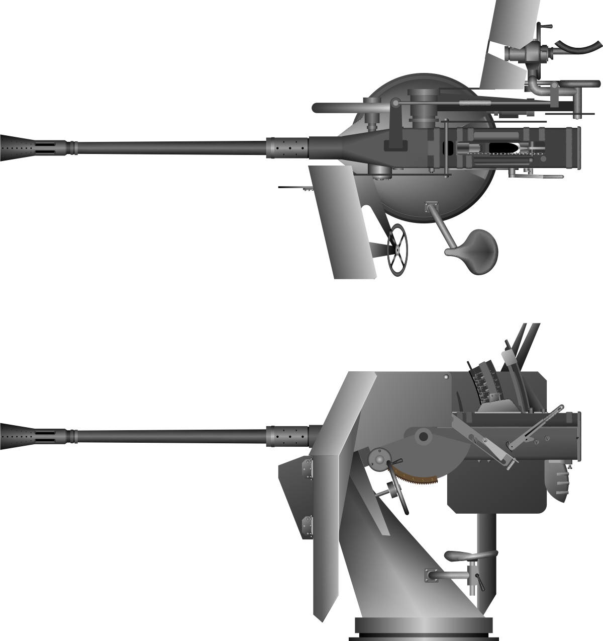

Fig. 1. A Single 3.7cm Flak M42U gun on the LM 43U mount.
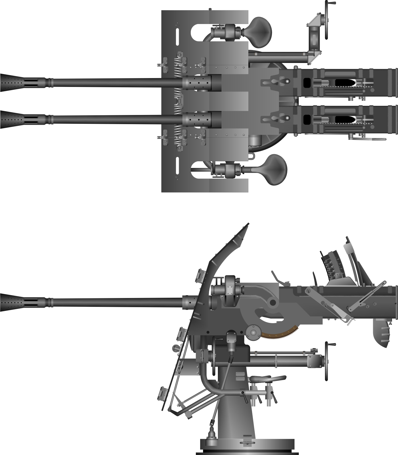

Fig. 2. A Twin 3.7cm Flak M42U guns on the LM 42U mount.

Offline SG

  • Admiral
  • *
  • Posts: 661
    • https://3xblackcats.wordpress.com/
Re: VIIC/41 - Schematices drawing
« Reply #1188 on: 17 Feb , 2014, 07:19 »
GREAT WORK SIMON!!!!

Offline Rokket

  • Administrator
  • *
  • Posts: 2,362
  • Gender: Male
  • Submarine Enthusiast
    • AMP - Accurate Model Parts
Re: VIIC/41 - Schematices drawing
« Reply #1189 on: 18 Feb , 2014, 00:36 »
as always!
AMP - Accurate Model Parts - http://amp.rokket.biz

Offline SnakeDoc

  • Admiral
  • *
  • Posts: 536
  • Gender: Male
    • Torpedo Vorhaltrechner Project
Re: VIIC/41 - Schematices drawing
« Reply #1190 on: 20 Feb , 2014, 12:40 »
Hi,


Simon, great drawings, as always and interesting conclusions about two styles of the piston.


Schnorchel mast is raised and lowered by the Schnorchel piston that is controlled by two hand wheels in the control room which activate a hydraulic mechanism. One hand-wheel is turned to "Open" for rising, when the Schnorchel is to be lowered, this wheel must be in the "Closed" position and the other wheel turned to "Open".


I will quote your post from another thread:
 
While doing some more research on the Schnorchel today, I came acoress this:

"Raising and lowering are controlled by hand wheels in the control room which activate a hydraulic mechanism.  One hand-wheel is turned to "Open" for raising; when the schnorchel is to be lowered, this wheel must be on "Closed" and the other wheel turned to "Open""

From the NAVY DEPARTMENT OFFICE OF THE CHIEF OF NAVAL OPERATIONS WASHINGTON Final Report - G/Serial 32 REPORT ON THE INTERROGATION OF SURVIVORS FROM U-575 SUNK 13 MARCH 1944 http://www.uboatarchive.net/U-575INT.htm

I was able to location the two 'Hand wheel' on U-995 ;D


http://www.kubische-panoramen.de/index.php?id_id=5379


http://models.rokket.biz/index.php?topic=121.msg10505#msg10505


Actually, now I think, that valves you had identified are hull valves for the hydraulic oil lines. The control valve is the valve here:

It's kind of change-over valve. It is also visible on the drawing provided by Tore (item no. 6, the hull valves - items no. 5).


Of course you are aware of the lockingpins in upright and lowered position.
Knowing your interest for details I shall point out the schnorkel position indicator placed in the forward controlroom, see photo and don`t be confused by the red drain cock on the voicepipe. The double indicatorpointers are very much like some pointers on boardvalves.


Tore, it seems you have great time in Africa :)
Great drawing anyway. The information about indicator pointers is also very interesting.
What is the heating connection (item no 11)?


--
Thanks, regards
Maciek

Offline NZSnowman

  • Admiral4
  • *
  • Posts: 2,419
  • Gender: Male
  • U-1308
    • U-1308 - Wikipedia
Re: VIIC/41 - Schematices drawing
« Reply #1191 on: 20 Feb , 2014, 13:33 »
Great timing!

I was just starting to look for the hull opening for the hydraulic.

Maciek, have you seen this drawing from http://thebattleofatlanticmuseum.ca/page20/page20.html.

The drawing seen accurate. I had estimated the pressure cylinder as 165 mm and accordingly to the drawing its 150 mm. Look like I am only out by 15 mm
 
Do you think the “St 20 · 2.5” is the diameter of the pipe and thickness?


Offline NZSnowman

  • Admiral4
  • *
  • Posts: 2,419
  • Gender: Male
  • U-1308
    • U-1308 - Wikipedia
Re: VIIC/41 - Schematices drawing
« Reply #1192 on: 20 Feb , 2014, 13:44 »
I just checked the hull opening for the hydraulic on U-955 and drawing, they are the same, between ribbing number 47 and 48 :)

Offline tore

  • Tore
  • *
  • Posts: 2,539
  • Gender: Male
Re: VIIC/41 - Schematices drawing
« Reply #1193 on: 20 Feb , 2014, 13:54 »
Hi Maciek.
Just returned from Africa today and a bit off track after some 15 hours flight incl. waiting at airports. However before I returned I made a sketch showing my assumption of the reality matching the sketch. You are of course Right that the shape of the handwheels shown on the photo indicated pressure oil or even luboil. Any how the rising/lowering schnorchel handle is the "ringhandle" as you pointed out, the two boardvalves of the system having luboil handwheels are the supply- and return boardvalves of the system, the returnpipe has a shutoff valve ( lowering speed valve) joining the hydraulic returnpipe from the navigation periscope hoist, whereas the schnorchel supply shutoff ( lifting speed)valve having a wheel of drinkingwater or pressureoil ( hydraulic oil) has of course its own connection to the hydraulic pressure oil system. We find these mixing of handwheels quite often on the U 995. For the schnorchel system I guess this might be because the installation was done in March- April 1945 in Trondheim and the supply of parts were short and they used the closest available handwheels. The indicated heating cable I cannot remember as the U 995 was an artic operating boat it could be for deicing of the ringfloat, we never used such a deicing. My idea would be a wire connection for the radardetector.
Tore

Offline SnakeDoc

  • Admiral
  • *
  • Posts: 536
  • Gender: Male
    • Torpedo Vorhaltrechner Project
Re: VIIC/41 - Schematices drawing
« Reply #1194 on: 20 Feb , 2014, 14:00 »
Maciek, have you seen this drawing from http://thebattleofatlanticmuseum.ca/page20/page20.html.
No, I haven't. Thanks for notifying.

Do you think the “St 20 · 2.5” is the diameter of the pipe and thickness?

Can be. St can stand for Stahl (Steel). Although I have met designation of diameter only as Leitungsdurchmesser innen and Leitungsdurchmesser außen. But it means nothing in this case. I do not know diameters of the hydraulic oil lines, but they can be estimated from photos.
 
I just checked the hull opening for the hydraulic on U-955 and drawing, they are the same, between ribbing number 47 and 48 :)


:)


--
Regards
Maciek

Offline SnakeDoc

  • Admiral
  • *
  • Posts: 536
  • Gender: Male
    • Torpedo Vorhaltrechner Project
Re: VIIC/41 - Schematices drawing
« Reply #1195 on: 20 Feb , 2014, 14:03 »


Just returned from Africa today and a bit off track after some 15 hours flight incl. waiting at airports. However before I returned I made a sketch showing my assumption of the reality matching the sketch. You are of course Right that the shape of the handwheels shown on the photo indicated pressure oil or even luboil. Any how the rising/lowering schnorchel handle is the "ringhandle" as you pointed out, the two boardvalves of the system having luboil handwheels are the supply- and return boardvalves of the system, the returnpipe has a shutoff valve ( lowering speed valve) joining the hydraulic returnpipe from the navigation periscope hoist, whereas the schnorchel supply shutoff ( lifting speed)valve having a wheel of drinkingwater or pressureoil ( hydraulic oil) has of course its own connection to the hydraulic pressure oil system. We find these mixing of handwheels quite often on the U 995. For the schnorchel system I guess this might be because the installation was done in March- April 1945 in Trondheim and the supply of parts were short and they used the closest available handwheels. The indicated heating cable I cannot remember as the U 995 was an artic operating boat it could be for deicing of the ringfloat, we never used such a deicing. My idea would be a wire connection for the radardetector.
Tore, thank you for your explanation and the sketch. It confirms my assumptions.
--
Regards
Maciek

Offline NZSnowman

  • Admiral4
  • *
  • Posts: 2,419
  • Gender: Male
  • U-1308
    • U-1308 - Wikipedia
Re: VIIC/41 - Schematices drawing
« Reply #1196 on: 20 Feb , 2014, 21:57 »
I was able to workout the openings for the hydraulic


Offline tore

  • Tore
  • *
  • Posts: 2,539
  • Gender: Male
Re: VIIC/41 - Schematices drawing
« Reply #1197 on: 23 Feb , 2014, 01:41 »
Simon
Schnorchelmast.
Looking at your  three positioning drawings of the schnorchel mast I believe you have the hydraulic connectingrod and the mastcrank a bit displaced. There are considerable forces to rise the mast and you want to have the rod and mastcrank at the optimal position for transferring the forces. Hence the connection should be 45 degrees on both side of the fulcrums vertical as I have tried to indicate on the sketch. The details of the German sketch are pretty much accurate.
Tore

Offline tore

  • Tore
  • *
  • Posts: 2,539
  • Gender: Male
Re: VIIC/41 - Schematices drawing
« Reply #1198 on: 23 Feb , 2014, 04:09 »
Simon.
In order to try to explain a bit more about the mechanical physics behind my last comment, I have copied the drawing which I believe might be your source for the schnorchel crankposition. When you decompose the graphic of the forces on the connectingrod when the mast is almost upright you see that a substantial part of the liftingforce is wasted in sideforces which has to be taken up by side thrust on the pistonrod guides which you don`t want. On the 2x45 crank degrees to the vertical of the fulcrum you have some minor sideforces but substantial more shall be utilised as lifting force. I believe the  German sketch below is incorrect and the other German sketch in my previous post is correct.
Tore
« Last Edit: 23 Feb , 2014, 04:12 by tore »

Offline NZSnowman

  • Admiral4
  • *
  • Posts: 2,419
  • Gender: Male
  • U-1308
    • U-1308 - Wikipedia
Re: VIIC/41 - Schematices drawing
« Reply #1199 on: 23 Feb , 2014, 12:09 »
Hi Tore

Thanks for the information angle!

I original never used any source for the schnorchel crank position, I do not think it was important.