Author Topic: VIIC/41 - Schematices drawing  (Read 589011 times)

0 Members and 11 Guests are viewing this topic.

Offline NZSnowman

  • Admiral4
  • *
  • Posts: 2,419
  • Gender: Male
  • U-1308
    • U-1308 - Wikipedia
Re: VIIC/41 - Schematices drawing
« Reply #1400 on: 05 Apr , 2016, 19:58 »
http://www.ebay.de/itm/U-1305-M-51575-U-Boot-13-9-1944-U-Boat-Indienststellung-Front-33-flottille-5-/401101335394?hash=item5d6380ab62:g:xQMAAOSwbwlXA~bq

The part to look out for is just behind the saddle tank, at the surface of the water. There are a collection of small round holes here (13 in each group - 6 on top row, 7 on bottom row). Have you seen this before? It is new to me.

This is new to me, I have not noted this before.

I checked my photo's collection and I also found it on U-250 & you can also see it in this photo below.

http://www.ebay.de/itm/Foto-U-Boot-Indienststellung-2-Baulehrkompanie-U-Danzig-Kriegsmarine-Polen-G-/311582946487?hash=item488bca74b7:g:9hMAAOSwJblXAW~t

http://www.ebay.de/itm/Foto-U-Boot-Indienststellung-2-Baulehrkompanie-U-Danzig-Kriegsmarine-Polen-F-/311582945950?hash=item488bca729e:g:l6AAAOSwQgpXAW~F

Firstly there is a barrel container sticking out of the lower platform on the port side. Secondly the ammo container lids look to be the upper colour (the twin 20mm gun can be seen to be gunmetal and is noticeably darker than the ammo lids.

There are several more in this series (just type in "U-boot foto, Danzig" and they will all be there) and they are all good quality.

Dougie, did you see the 3 drain holes in the middle of the casting of the lower platform? Never seen that before also :o

http://www.ebay.de/itm/Foto-U-Boot-Indienststellung-2-Baulehrkompanie-U-Danzig-Kriegsmarine-Polen-K/311582947778?_trksid=p2047675.c100005.m1851&_trkparms=aid%3D222007%26algo%3DSIC.MBE%26ao%3D1%26asc%3D35939%26meid%3D9f7c82fa2ebd46ee8802a7f4d910ca82%26pid%3D100005%26rk%3D3%26rkt%3D6%26sd%3D311582945950

http://www.ebay.de/itm/Foto-U-Boot-Indienststellung-2-Baulehrkompanie-U-Danzig-Kriegsmarine-Polen-F-/311582945950?hash=item488bca729e:g:l6AAAOSwQgpXAW~F

Firstly there is a barrel container sticking out of the lower platform on the port side.

Never seem the barrel container like that before also :o However, if you look at the photo below, the flap does not look waterproof and its look totally different to the normal ones, perhaps this container was used for something other?

http://www.ebay.de/itm/Foto-U-Boot-Indienststellung-2-Baulehrkompanie-U-Danzig-Kriegsmarine-Polen-E-/361526318659?hash=item542ca5d643:g:kJoAAOSwQgpXAW-h

« Last Edit: 05 Apr , 2016, 21:04 by NZSnowman »

Offline dougie47

  • Administrator
  • *
  • Posts: 758
Re: VIIC/41 - Schematices drawing
« Reply #1401 on: 06 Apr , 2016, 11:09 »
Hi Simon,

No, I don't recall seeing those three holes in the lower platform before. You may have seen them but notice there are at least four round drainage holes on the underside of the upper platform. U 1056 had these too.

I see what you mean about the lids on the barrel containers, this one is different to the norm. I still think it must be for a barrel due to the shape and because there was often a barrel container somewhere on the lower platform. I note that U 1305 had two containers, one on either side, I wonder what U 1308 had?

Regarding the small round holes near the waterline. These are in the position where the three elongated holes usually were. Perhaps on U 1305 and U 250 they drilled these round holes instead of cutting out the three large elongated drain holes. However, I know when I have drilled out a vent I have drilled a line of round holes around the area, popped out the part and then filed the edges of the vent with a file. The pattern of round holes on U 1305 is a bit reminiscent of this process so I wonder if a worker could possibly be halfway through a similar process?

Cheers,

Dougie 

Offline NZSnowman

  • Admiral4
  • *
  • Posts: 2,419
  • Gender: Male
  • U-1308
    • U-1308 - Wikipedia
Re: VIIC/41 - Schematices drawing
« Reply #1402 on: 06 Apr , 2016, 13:27 »
I note that U 1305 had two containers, one on either side, I wonder what U 1308 had?

To my knowledge there no photo's of U-1308, however, I may have recently found one at http://www.u-boot-archiv-cuxhaven.de. This photo may have been taken in February 1953 inside the CT of U-1308.

I have found one photo's of U-1306 at http://forum.sub-driver.com which is likely the most similar u-boat to U-1308 (It also have a Alberich coating. I have never see any pictures of U-1307 and I have no evidence that U1307 had Alberich).


Offline dougie47

  • Administrator
  • *
  • Posts: 758
Re: VIIC/41 - Schematices drawing
« Reply #1403 on: 06 Apr , 2016, 16:03 »
Hi Simon,

I don't have photos of U 1307 or U 1308 but if I ever do see them then I'll send to you.

The following is supposed to be of U 1306 (though it would be hard to be 100% about it as the source of the photo is unknown) -


Cheers,

Dougie

Offline Bad Karma

  • Lieutenant
  • *
  • Posts: 82
Re: VIIC/41 - Schematices drawing
« Reply #1404 on: 20 Apr , 2016, 08:10 »
hi,

Regarding this picture,it`s the U-968.


my best regards,

Ron.

________
Let's just say I was testing the bounds of reality. I was curious to see what would happen. That's all it was: curiosity.

Jim Morrison

Offline dougie47

  • Administrator
  • *
  • Posts: 758
Re: VIIC/41 - Schematices drawing
« Reply #1405 on: 20 Apr , 2016, 09:40 »
Hi Ron,

Many thanks for identifying the boat, very helpful.

Cheers,

Dougie

Offline Bad Karma

  • Lieutenant
  • *
  • Posts: 82
Re: VIIC/41 - Schematices drawing
« Reply #1406 on: 20 Apr , 2016, 10:17 »
Hi Dougie,

It was Axel Niestle who gave this boat a positive ID.

my best regards,

Ron.

________
Let's just say I was testing the bounds of reality. I was curious to see what would happen. That's all it was: curiosity.

Jim Morrison

Offline NZSnowman

  • Admiral4
  • *
  • Posts: 2,419
  • Gender: Male
  • U-1308
    • U-1308 - Wikipedia
Re: VIIC/41 - Schematices drawing
« Reply #1407 on: 26 Apr , 2016, 13:08 »
Hi Snowman, hi Dougie,

impressive picture many thanks for sharing.

Some thoughts about colours. Please take a look at the attached jpg "comparison". As a preliminary point it is just an example to underline my following remarks and not to raise a claim to have spotted the accurate colours.

Let's get started: On the left side you can see the original picture and on the right side my (fast) colour corrections. Photographers know that colour photos from this area has a red and a yellow cast due to the used material (I suppose Eastmann Kodak maybe "Kodakchrome" here). The yellow cast can be spotted very good in the clouds and the whole sky area. The red cast can be recognized in the rope and brown colored areas. The surface of the sea has IMO to much magenta and yellow so it looks to blue. The whole photo seems to be a little bit saturated and underexposed. Maybe this is a result from the scan process of the original photo or the photographer did not used the optimal aperture.

In addition to it: The central issue discussing about colours is that all forum members here can not see the identical correct colours due to non-calibrated displays or individual colour profile settings. Not to mention the various settings of the display like colour temperature, brightness, gamma and so on. This problem is well known in my profession (Graphic-Design and Prepress), we call it "individual colour aspects"  ;)


Regards
falo


Falo, could you please re-upload the colour corrected photograph. I did not save it the first time.

Thanks, Simon.

Offline falo

  • Admiral
  • *
  • Posts: 514
  • Gender: Male
Re: VIIC/41 - Schematices drawing
« Reply #1408 on: 26 Apr , 2016, 23:32 »
Hi Simon,


please find attached the re-upload.


Regards
falo

Offline NZSnowman

  • Admiral4
  • *
  • Posts: 2,419
  • Gender: Male
  • U-1308
    • U-1308 - Wikipedia
Re: VIIC/41 - Schematices drawing
« Reply #1409 on: 26 Apr , 2016, 23:40 »
Hi Simon,


please find attached the re-upload.


Regards
falo

Thanks  :)

Offline NZSnowman

  • Admiral4
  • *
  • Posts: 2,419
  • Gender: Male
  • U-1308
    • U-1308 - Wikipedia
Re: VIIC/41 - Schematices drawing
« Reply #1410 on: 08 May , 2016, 15:36 »
The winter is drawing nearly to the southern hemisphere, so I am winding down my U-boat research and drawings for another year. Thanks everyone for your help this year.


Offline falo

  • Admiral
  • *
  • Posts: 514
  • Gender: Male
Re: VIIC/41 - Schematices drawing
« Reply #1411 on: 09 May , 2016, 07:22 »
Hi Simon,


this summer break is a splendid opportunity to thank you in the meantime for this brillant thread.


Cheers and regards
falo

Offline NZSnowman

  • Admiral4
  • *
  • Posts: 2,419
  • Gender: Male
  • U-1308
    • U-1308 - Wikipedia
Re: VIIC/41 - Schematices drawing
« Reply #1412 on: 28 May , 2016, 15:32 »
Carl Zeiss U-boat 7x50 Binoculars


Offline Johann Vilthomsen

  • Lieutenant
  • *
  • Posts: 89
Re: VIIC/41 - Schematices drawing
« Reply #1413 on: 30 May , 2016, 02:14 »
NZ Snowman, your job is and will be an essential tool for lovers of German submarines.
I can not wait to see your work finished.
Thank you very much for it.

Offline David83

  • Lieutenant (jg)
  • *
  • Posts: 70
  • Gender: Male
Re: VIIC/41 - Schematices drawing
« Reply #1414 on: 30 May , 2016, 10:15 »
Realy great job as always never seeing so much love and effort to reconstruct German Submarines .

wbr David

Offline SG

  • Admiral
  • *
  • Posts: 661
    • https://3xblackcats.wordpress.com/
Re: VIIC/41 - Schematices drawing
« Reply #1415 on: 30 May , 2016, 10:43 »
just Beautiful
Amazing progress Simon!

Offline SnakeDoc

  • Admiral
  • *
  • Posts: 536
  • Gender: Male
    • Torpedo Vorhaltrechner Project
Re: VIIC/41 - Schematices drawing
« Reply #1416 on: 30 May , 2016, 12:03 »
Hi Gentlemen,


Simon, great work. I have got question - do you have any drawings or photos of this "dark-grey" UZO column part?
I mean the part with one large hand-wheel at one side and smaller knob at the other side.


Simon, long time ago we have discussed the construction of the torpedo tubes. Below is the photo:
https://flic.kr/p/G2hp31
that presents (I suppose, because I cannot be sure), the lower part of the MBT 5 (looking upward) with two outer torpedo tubes sections.
I guess, you will find it interesting.


--
Regards
Maciek

Offline NZSnowman

  • Admiral4
  • *
  • Posts: 2,419
  • Gender: Male
  • U-1308
    • U-1308 - Wikipedia

Offline NZSnowman

  • Admiral4
  • *
  • Posts: 2,419
  • Gender: Male
  • U-1308
    • U-1308 - Wikipedia
Re: VIIC/41 - Schematices drawing
« Reply #1418 on: 30 May , 2016, 14:44 »
... I can not wait to see your work finished.

Perhaps next year I could be ready to present my drawings. I am doing a little test of my drawings for myself now.


Offline falo

  • Admiral
  • *
  • Posts: 514
  • Gender: Male
Re: VIIC/41 - Schematices drawing
« Reply #1419 on: 30 May , 2016, 23:15 »
Hi Snowman,


please enter an order for that book for me. Are you planing to publish the book by yourself and release it by Amazon?


Regards
falo
« Last Edit: 03 Jun , 2016, 04:39 by falo »

Offline Bob Tomlin

  • Ensign
  • *
  • Posts: 34
  • Gender: Male
Re: VIIC/41 - Schematices drawing
« Reply #1420 on: 01 Jun , 2016, 14:28 »
Stunning work Simon. I'd be down for a copy of that book too please.
Hoping you'll start having a look at Type IX's too one day.
Cheers Bob.

Offline Johann Vilthomsen

  • Lieutenant
  • *
  • Posts: 89
Re: VIIC/41 - Schematices drawing
« Reply #1421 on: 02 Jun , 2016, 04:16 »
Great Idea Simon, I buy it!!  :)

Offline Anakin

  • Sir Submarine
  • Lt Cdr
  • *
  • Posts: 220
  • Gender: Male
Re: VIIC/41 - Schematices drawing
« Reply #1422 on: 02 Jun , 2016, 11:13 »
Count me in!  ;) Want one too...

Offline NZSnowman

  • Admiral4
  • *
  • Posts: 2,419
  • Gender: Male
  • U-1308
    • U-1308 - Wikipedia
Re: VIIC/41 - Schematices drawing
« Reply #1423 on: 07 Jun , 2016, 02:55 »
Hi Snowman,


please enter an order for that book for me. Are you planing to publish the book by yourself and release it by Amazon?


Regards
falo

I not sure how I will do it yet. Not sure what are my option yet.

I sent my test book away to the printer yesterday. Should get it back in 1 or 2 weeks. Cannot wait to see how it turn outs. When I get it back I will post some pictures of it.

Offline NZSnowman

  • Admiral4
  • *
  • Posts: 2,419
  • Gender: Male
  • U-1308
    • U-1308 - Wikipedia
Re: VIIC/41 - Schematices drawing
« Reply #1424 on: 29 Jul , 2016, 19:25 »
I got my test book back from the printer. Here are a few pictures.


Offline Capt Kremin

  • Commander
  • *
  • Posts: 273
  • Gender: Male
Re: VIIC/41 - Schematices drawing
« Reply #1425 on: 30 Jul , 2016, 06:40 »
Hi Simon


Looking Good!


Regards
Jon
"Here's Peter Jason Quill, He's also called Starlord",
"Who calls him that?",
"Himself Mostly".

Offline Johann Vilthomsen

  • Lieutenant
  • *
  • Posts: 89
Re: VIIC/41 - Schematices drawing
« Reply #1426 on: 01 Aug , 2016, 01:08 »
Nice Job Simon!  :)

Offline SG

  • Admiral
  • *
  • Posts: 661
    • https://3xblackcats.wordpress.com/
Re: VIIC/41 - Schematices drawing
« Reply #1427 on: 01 Aug , 2016, 11:42 »
Well done Simon! Looking forward to get a copy anytime soon!
keep up the excellent job !!

Offline NZSnowman

  • Admiral4
  • *
  • Posts: 2,419
  • Gender: Male
  • U-1308
    • U-1308 - Wikipedia
Re: VIIC/41 - Schematices drawing
« Reply #1428 on: 04 Oct , 2016, 12:37 »
Hi All

I hope you all had a great summer or winter. I have finish yet again winter in New Zealand. I hope to start my U-boat drawings and research in a few weeks after I sort out my life. Also to let you know that my U-boat drawings and research will be come out in ‘drops and drabs’ for the next three years as I will be starting a Ph.D. in February.

Anyway, I have posted some links to my drawings. These drawings illustrate the level of detail of my 3-D model. They are large and detail, around 300 dpi at A3 size and between 4 and 10 MB in size. Would make a great large poster for someone room. Please let me know what you think of them, thanks.


https://farm9.staticflickr.com/8362/30081043286_f9fa0936db_o_d.jpg

https://farm6.staticflickr.com/5797/30031945651_dfb159fc9b_o_d.jpg

https://farm9.staticflickr.com/8267/29821014350_a107779563_o_d.jpg

Offline falo

  • Admiral
  • *
  • Posts: 514
  • Gender: Male
Re: VIIC/41 - Schematices drawing
« Reply #1429 on: 04 Oct , 2016, 13:33 »
Hi Snowman,


great work, thanks for sharing the drawings. Just a question: Will you "coat" finally the boat with Alberich tiles?


Regards
falo


Offline NZSnowman

  • Admiral4
  • *
  • Posts: 2,419
  • Gender: Male
  • U-1308
    • U-1308 - Wikipedia
Re: VIIC/41 - Schematices drawing
« Reply #1430 on: 04 Oct , 2016, 13:44 »
Will you "coat" finally the boat with Alberich tiles?

I think I will add the Alberich tiles to a separate layer to my model. I would like to accurately model the correct alignment and attachment method of each individual tile over the whole U-boat. I think I have just enough photos and information to accurately do this.

Offline pumpjet

  • Ensign
  • *
  • Posts: 27
  • Gender: Male
Re: VIIC/41 - Schematices drawing
« Reply #1431 on: 05 Oct , 2016, 19:00 »
HI Simon....

I'll take a copy of your book also. Do you have details yet,such as pricing???


Thanks

Bob

Offline NZSnowman

  • Admiral4
  • *
  • Posts: 2,419
  • Gender: Male
  • U-1308
    • U-1308 - Wikipedia
Re: VIIC/41 - Schematices drawing
« Reply #1432 on: 21 Oct , 2016, 02:01 »
I wonder what this could be the start of?  ;D ;D


Offline NZSnowman

  • Admiral4
  • *
  • Posts: 2,419
  • Gender: Male
  • U-1308
    • U-1308 - Wikipedia
Re: VIIC/41 - Schematices drawing
« Reply #1433 on: 23 Oct , 2016, 20:22 »
Exhaust Acces Hatch (left), Exhaust Outlet Control Valve Hatch (outer middle) and small Access Hatch (right). Central Access Hatch (Mid-line)

Brown = Deck, puple = Hatches, Yellow = Deck framing & Grey = Deck Casting

This images has been resized. Click to view original image.


This images has been resized. Click to view original image.


This images has been resized. Click to view original image.


This images has been resized. Click to view original image.


This images has been resized. Click to view original image.

Offline NZSnowman

  • Admiral4
  • *
  • Posts: 2,419
  • Gender: Male
  • U-1308
    • U-1308 - Wikipedia
Re: VIIC/41 - Schematices drawing
« Reply #1434 on: 28 Oct , 2016, 16:36 »
Stern - Anti-slip bumps, rivets and deck plates.


This images has been resized. Click to view original image.

Offline NZSnowman

  • Admiral4
  • *
  • Posts: 2,419
  • Gender: Male
  • U-1308
    • U-1308 - Wikipedia
Re: VIIC/41 - Schematices drawing
« Reply #1435 on: 28 Oct , 2016, 18:45 »
Main Dive Tank 1 Vent


This images has been resized. Click to view original image.

Offline NZSnowman

  • Admiral4
  • *
  • Posts: 2,419
  • Gender: Male
  • U-1308
    • U-1308 - Wikipedia
Re: VIIC/41 - Schematices drawing
« Reply #1436 on: 28 Oct , 2016, 22:19 »
Bollards


This images has been resized. Click to view original image.

Offline NZSnowman

  • Admiral4
  • *
  • Posts: 2,419
  • Gender: Male
  • U-1308
    • U-1308 - Wikipedia
Re: VIIC/41 - Schematices drawing
« Reply #1437 on: 29 Oct , 2016, 02:24 »

This images has been resized. Click to view original image.
Error: I just noted an error in this image, there are no rivets on the last plate of deck (foreground), it should be wielded, not riveted.
« Last Edit: 29 Oct , 2016, 13:06 by NZSnowman »

Offline NZSnowman

  • Admiral4
  • *
  • Posts: 2,419
  • Gender: Male
  • U-1308
    • U-1308 - Wikipedia
Re: VIIC/41 - Schematices drawing
« Reply #1438 on: 29 Oct , 2016, 22:54 »
Rear jumping wire supports


This images has been resized. Click to view original image.


This images has been resized. Click to view original image.


This images has been resized. Click to view original image.


This images has been resized. Click to view original image.


This images has been resized. Click to view original image.

Offline falo

  • Admiral
  • *
  • Posts: 514
  • Gender: Male
Re: VIIC/41 - Schematices drawing
« Reply #1439 on: 30 Oct , 2016, 03:38 »
Hi Showmann,


thanks again for sharing, amazing work!


I'am wondering if the metal plates of the wooden deck were coated with Alberich tiles (for example U 1105)?
If the plates were coated all the rivets had to be removed to get a smooth surface so the tiles could stick on the metal. What do you think?


Thanks in advance
falo

Offline Bob Tomlin

  • Ensign
  • *
  • Posts: 34
  • Gender: Male
Re: VIIC/41 - Schematices drawing
« Reply #1440 on: 30 Oct , 2016, 05:22 »
Hi Simon,


I'm in awe of your superdetailed schematics and these decks really look the part.


As someone who gets possibly a little too obsessed with details sometimes, I'd recently been delving into the world of non-slip stud patterns on the bow and stern plates (mainly on type IXs, but also type VIIs).
Looking at photographs, I'd pretty much convinced myself at one stage that the pattern on most boats was this one - not to scale - (I'm calling this Type A):-


With this pattern you can make equilateral hexagons out of the studs.
Am I right in thinking that my eyes are looking at this pattern in your schematics here Simon?


I realise that there's probably some variation with boats out of different shipyards, but just wanted to make sure you'd also seen the boats with this type of pattern - not to scale again - (which I'm calling type B):-


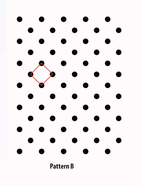
With this pattern, you can make square shapes within the studs.


I'm just mentioning it because as I said, for a while I was convinced that I was looking at pattern A in photos, because of the effects of perspective, when I was actually looking at 'B'.
For example, when looking from a low angle from the stern, my eyes were seeing the hexagons, but when I carried out a small experiment (yes it was becoming a sort of obsession), I realised it was the effect of perspective.


Of course it's very hard to tell properly in photos unless they are taken from almost a plan view of the deck and close enough to see the studs.
I have definitely got photos of the type B pattern on type VIIs but have not yet come across one that definitely shows a type A.
I'd be very interested if you've come across a photo that definitively shows a 'Type A' pattern though?
I've been looking for a close-up on the U-995 to see what that has, but not found one yet.


Cheers Bob.


Offline NZSnowman

  • Admiral4
  • *
  • Posts: 2,419
  • Gender: Male
  • U-1308
    • U-1308 - Wikipedia
Re: VIIC/41 - Schematices drawing
« Reply #1441 on: 30 Oct , 2016, 12:05 »
Hi Showmann,


thanks again for sharing, amazing work!


I'am wondering if the metal plates of the wooden deck were coated with Alberich tiles (for example U 1105)?
If the plates were coated all the rivets had to be removed to get a smooth surface so the tiles could stick on the metal. What do you think?


Thanks in advance
falo

I don’t have any photo's that are clear enough to tell if the Alberich tiles are on the metal plates of the wooden deck, sorry. I will keep my eyes open for any evidence.

Offline NZSnowman

  • Admiral4
  • *
  • Posts: 2,419
  • Gender: Male
  • U-1308
    • U-1308 - Wikipedia
Re: VIIC/41 - Schematices drawing
« Reply #1442 on: 30 Oct , 2016, 13:21 »
Hi Bob

Very interesting discussion.

It’s been a while since I did my non-slip stud patterns research. The first thing I noticed while doing my research was there are several different patterns of non-slip stud patterns. This difference is mostly seen between the plates from inside and outside the U-boat.
 
Of the ‘circular’ non-slip stud patterns, there are two style, Style A & B. From my research, I have found style A is virtually only the on bow and stern. Style B is mainly on the inside of the U-boat and on some of the metal deck hatches (but I believe style B has be put on some early Type VIIC’s bow and stern also).

Like you said, finding good photos to be 100% sure it’s very hard, however, I rechecked my photos again this morning, and with the evidence I have I am still confident that most Type VIIC’s used style A on their bow and stern.

I have very few photos of the Type IX, but I yet to see Style A on this boat, I have only seen Style B on the Type IX.

Offline NZSnowman

  • Admiral4
  • *
  • Posts: 2,419
  • Gender: Male
  • U-1308
    • U-1308 - Wikipedia
Re: VIIC/41 - Schematices drawing
« Reply #1443 on: 30 Oct , 2016, 19:46 »
Hi Bob

Very interesting discussion.

It’s been a while since I did my non-slip stud patterns research. The first thing I noticed while doing my research was there are several different patterns of non-slip stud patterns. This difference is mostly seen between the plates from inside and outside the U-boat.
 
Of the ‘circular’ non-slip stud patterns, there are two style, Style A & B. From my research, I have found style A is virtually only the on bow and stern. Style B is mainly on the inside of the U-boat and on some of the metal deck hatches (but I believe style B has be put on some early Type VIIC’s bow and stern also).

Like you said, finding good photos to be 100% sure it’s very hard, however, I rechecked my photos again this morning, and with the evidence I have I am still confident that most Type VIIC’s used style A on their bow and stern.

I have very few photos of the Type IX, but I yet to see Style A on this boat, I have only seen Style B on the Type IX.

Thanks for the PM
 
I rechecked a third time all the photo's I have. The best photo I believe is from Tore while he was standing on the bow during a practice torpedo firing. In this photo there is strong evidence to suggest Style B.
 
However, I think the very best photo is found in the book by E. Wetzel on U-995 on page 91. Here a photo of U-338 is extremely clear and almost if not perpendicular to the camera. This photo clearly indicates Style B.
 
Looks like I will have to changed my non-slip stud patterns :'(
« Last Edit: 31 Oct , 2016, 00:24 by NZSnowman »

Offline NZSnowman

  • Admiral4
  • *
  • Posts: 2,419
  • Gender: Male
  • U-1308
    • U-1308 - Wikipedia
Re: VIIC/41 - Schematices drawing
« Reply #1444 on: 30 Oct , 2016, 20:11 »
Port side wooden pole

Dougie, here my 3-D model of the large pole found on the port side of the boat.


This images has been resized. Click to view original image.


This images has been resized. Click to view original image.

Offline NZSnowman

  • Admiral4
  • *
  • Posts: 2,419
  • Gender: Male
  • U-1308
    • U-1308 - Wikipedia
Re: VIIC/41 - Schematices drawing
« Reply #1445 on: 31 Oct , 2016, 00:23 »
Hi Bob

Here my new non-slip stud patterns (Upper section), Style A (lower). I also made the stud smaller, they are now 7.5 mm (D) by 3.0 mm (H); older ones were 10 mm (D) by 5 mm (H). What you think?


This images has been resized. Click to view original image.

Offline dougie47

  • Administrator
  • *
  • Posts: 758
Re: VIIC/41 - Schematices drawing
« Reply #1446 on: 31 Oct , 2016, 15:20 »
Hi Simon,

Very nice on the wooden pole. For the early VIIC decks my estimate for the length of the wooden pole (both the one on the forward deck and the long one on the aft deck) was a length of 6 metres long.

The early boats also could have a shorter pole on the aft deck on the starboard side; my estimate for this one was 4 metres.

Going by the photo of U 1305 at commissioning, it is hard to tell but it looks like it might be the same length as 12 free-flooding vents? This would make it around 6 metres long.

Cheers,

Dougie

Offline Bob Tomlin

  • Ensign
  • *
  • Posts: 34
  • Gender: Male
Re: VIIC/41 - Schematices drawing
« Reply #1447 on: 31 Oct , 2016, 15:33 »
Hi Simon, sorry for the delay in getting back to you (stuck in work all day).
Thanks for having another look at the studs for me. Yes I find it quite difficult looking at the patterns in photos and trying to work it out with perspective (I certainly felt like my eyes were going 'dotty').
From what I could see on the bow of the U-995 in a photo, I thought the studs looked like pattern B also. Just seen a photo of pattern B on U-612 also (early boat).


The studs look great in your schematic too.
I am interested in what the spacings should be in 72nd scale. Revell have got the type B on their U-505 kit and look (to me) to have horizontal and vertical spacings at approx 1.2mm? (86.4mm if you scaled it up).


I would very much like to know if you do come across a clear example of a Type A in a photo sometime. If there was an industry standard it would make things a lot easier.


Great artwork as always.
Thanks and Cheers, Bob.


Offline NZSnowman

  • Admiral4
  • *
  • Posts: 2,419
  • Gender: Male
  • U-1308
    • U-1308 - Wikipedia
Re: VIIC/41 - Schematices drawing
« Reply #1448 on: 04 Nov , 2016, 22:25 »
The bow reserve torpedo container hatches


This images has been resized. Click to view original image.


This images has been resized. Click to view original image.


This images has been resized. Click to view original image.


Offline NZSnowman

  • Admiral4
  • *
  • Posts: 2,419
  • Gender: Male
  • U-1308
    • U-1308 - Wikipedia
Re: VIIC/41 - Schematices drawing
« Reply #1449 on: 05 Nov , 2016, 14:12 »
Just a remember to everyone, many of my 3-D models can be found at:

https://3dwarehouse.sketchup.com/collection.html?id=u4a2facb6-00be-441c-a5e5-ffd7a3c3549d

Offline NZSnowman

  • Admiral4
  • *
  • Posts: 2,419
  • Gender: Male
  • U-1308
    • U-1308 - Wikipedia
Re: VIIC/41 - Schematices drawing
« Reply #1450 on: 05 Nov , 2016, 14:35 »
Rear jumping wire supports


This images has been resized. Click to view original image.


Update: I found a better wartime photo of the Rear jumping wire support frame. This photo corrected the position of this support frame compared to the Type VIIC’s plans and clearly indicated the methods of attachment for the internal support pole. This new model reflects the changes.


This images has been resized. Click to view original image.
« Last Edit: 29 Nov , 2016, 00:23 by NZSnowman »

Offline NZSnowman

  • Admiral4
  • *
  • Posts: 2,419
  • Gender: Male
  • U-1308
    • U-1308 - Wikipedia
Re: VIIC/41 - Schematices drawing
« Reply #1451 on: 05 Nov , 2016, 20:05 »
Dougie, here C5 from the Accurate Model Parts 72-02 1/72nd Type VIIC U-Boat Deck & Floods Set (page 10)


This images has been resized. Click to view original image.


This images has been resized. Click to view original image.

Offline NZSnowman

  • Admiral4
  • *
  • Posts: 2,419
  • Gender: Male
  • U-1308
    • U-1308 - Wikipedia
Re: VIIC/41 - Schematices drawing
« Reply #1452 on: 18 Nov , 2016, 00:02 »
Finding original German measurements for the Conning Tower is very rare. I have collected all the original measurement for the Conning Tower I have and prepared this plan for people.

Happy viewing :)


This images has been resized. Click to view original image.

PS. I also have a pdf of this if you would like it.

Offline Johann Vilthomsen

  • Lieutenant
  • *
  • Posts: 89
Re: VIIC/41 - Schematices drawing
« Reply #1453 on: 21 Nov , 2016, 03:00 »
Thank You!!!!!  :D

Offline NZSnowman

  • Admiral4
  • *
  • Posts: 2,419
  • Gender: Male
  • U-1308
    • U-1308 - Wikipedia
Re: VIIC/41 - Schematices drawing
« Reply #1454 on: 26 Nov , 2016, 21:56 »
Have anyone got any photo's of the capstan?

Offline NZSnowman

  • Admiral4
  • *
  • Posts: 2,419
  • Gender: Male
  • U-1308
    • U-1308 - Wikipedia
Re: VIIC/41 - Schematices drawing
« Reply #1455 on: 29 Nov , 2016, 00:20 »
Exhaust Gas Blowing Manifold

The exhaust gas blow system used exhaust gas from the main engines to assist with blowing the tanks to raise the U-boat. A pipe extending forward from the main engine exhaust valves, to led forward to a manifold located over the control room. From the manifold, smaller pipes runs to 8 tanks around the u-boat. The eight associated valves in the manifold were operable from within the control room.


Fig. 1. Starborad. (This images has been resized. Click to view original image).


This images has been resized. Click to view original image.


This images has been resized. Click to view original image.


This images has been resized. Click to view original image.


This images has been resized. Click to view original image.
Yellow = Exhaust Gas piping.
Dark Gray = Pressure Hull.
Light Gray = Bridge Casting.
Purple = Deck Hatches.
Brown = Wooden Deck.
Dark Yellow = Deck Frame


This images has been resized. Click to view original image.


This images has been resized. Click to view original image.
« Last Edit: 29 Nov , 2016, 12:06 by NZSnowman »

Offline NZSnowman

  • Admiral4
  • *
  • Posts: 2,419
  • Gender: Male
  • U-1308
    • U-1308 - Wikipedia
Re: VIIC/41 - Schematices drawing
« Reply #1456 on: 03 Dec , 2016, 15:34 »
Building at Type VIIC/41


This images has been resized. Click to view original image.


This images has been resized. Click to view original image.


This images has been resized. Click to view original image.


This images has been resized. Click to view original image.


This images has been resized. Click to view original image.

Offline falo

  • Admiral
  • *
  • Posts: 514
  • Gender: Male
Re: VIIC/41 - Schematices drawing
« Reply #1457 on: 04 Dec , 2016, 02:12 »
Hi Snowman,


thanks for the 3-D-drawings. To repeat myself I'am delighted with your thread.


Just one question about the sub construction of the wooden deck: Do you have a a complete top view of the metallic construction – from bow to stern?


Once again thanks for sharing and best regards!
falo

Offline NZSnowman

  • Admiral4
  • *
  • Posts: 2,419
  • Gender: Male
  • U-1308
    • U-1308 - Wikipedia
Re: VIIC/41 - Schematices drawing
« Reply #1458 on: 04 Dec , 2016, 10:36 »
Hi Snowman,


thanks for the 3-D-drawings. To repeat myself I'am delighted with your thread.


Just one question about the sub construction of the wooden deck: Do you have a a complete top view of the metallic construction – from bow to stern?


Once again thanks for sharing and best regards!
falo

The deck framing is about 80% finish. I am still working on it.

  • Most of the stern section is finish just need to check a few things.
  • The mid-section is finish (just remember that this deck frame is for a Type VIIC/41 and a late war Type VIIC, additional hatches and schnorchel).
  • Bow section is not finish, I need better wartime photo's of the framing to finish this section.

Below is a extra large version of the deck framing.


This images has been resized. Click to view original image.


Offline falo

  • Admiral
  • *
  • Posts: 514
  • Gender: Male
Re: VIIC/41 - Schematices drawing
« Reply #1459 on: 05 Dec , 2016, 02:42 »
Hi Snowman,


thank you very much!


Regards
falo

Offline NZSnowman

  • Admiral4
  • *
  • Posts: 2,419
  • Gender: Male
  • U-1308
    • U-1308 - Wikipedia
Re: VIIC/41 - Schematices drawing
« Reply #1460 on: 09 Dec , 2016, 19:30 »
Vent valve for main ballast and reserve fuel oil tanks 2 and 4.


This images has been resized. Click to view original image.


This images has been resized. Click to view original image.


This images has been resized. Click to view original image.


This images has been resized. Click to view original image.


This images has been resized. Click to view original image.


This images has been resized. Click to view original image.

Offline NZSnowman

  • Admiral4
  • *
  • Posts: 2,419
  • Gender: Male
  • U-1308
    • U-1308 - Wikipedia
Re: VIIC/41 - Schematices drawing
« Reply #1461 on: 11 Dec , 2016, 11:57 »
Hi Snowman,


thanks for the 3-D-drawings. To repeat myself I'am delighted with your thread.


Just one question about the sub construction of the wooden deck: Do you have a a complete top view of the metallic construction – from bow to stern?


Once again thanks for sharing and best regards!
falo

The deck framing is about 80% finish. I am still working on it.

  • Most of the stern section is finish just need to check a few things.
  • The mid-section is finish (just remember that this deck frame is for a Type VIIC/41 and a late war Type VIIC, additional hatches and schnorchel).
  • Bow section is not finish, I need better wartime photo's of the framing to finish this section.
Below is a extra large version of the deck framing.


This images has been resized. Click to view original image.


falo, here a update for the mid-section of the deck framing.


This images has been resized. Click to view original image.

Offline falo

  • Admiral
  • *
  • Posts: 514
  • Gender: Male
Re: VIIC/41 - Schematices drawing
« Reply #1462 on: 12 Dec , 2016, 11:50 »
Hi Snowman,

thank you very much. I have been a follower of this thread for years, IMO with "Schematices drawing" you are developing a masterpiece.

Best regards
falo

Offline NZSnowman

  • Admiral4
  • *
  • Posts: 2,419
  • Gender: Male
  • U-1308
    • U-1308 - Wikipedia
Re: VIIC/41 - Schematices drawing
« Reply #1463 on: 12 Dec , 2016, 12:26 »
Either by luck or good design, I was able to match the small pipe around the vent valve for main ballast and reserve fuel oil tanks 2 and 4 on the starboard side of the U-Boat ;D


Figure 1. U-1308. This images has been resized. Click to view original image.


Figure 2. U-570.

Offline NZSnowman

  • Admiral4
  • *
  • Posts: 2,419
  • Gender: Male
  • U-1308
    • U-1308 - Wikipedia
Re: VIIC/41 - Schematices drawing
« Reply #1464 on: 12 Dec , 2016, 14:21 »
Here a link to a small animation of U-1308 :)

https://www.youtube.com/watch?v=0qPLw79JFIU

Offline Johann Vilthomsen

  • Lieutenant
  • *
  • Posts: 89
Re: VIIC/41 - Schematices drawing
« Reply #1465 on: 13 Dec , 2016, 03:49 »
BRAVO! BRAVO!

It is a pleasure to see your work. Fascinating and educational.

Greetings!


Offline falo

  • Admiral
  • *
  • Posts: 514
  • Gender: Male
Re: VIIC/41 - Schematices drawing
« Reply #1466 on: 30 Dec , 2016, 10:47 »
Hi Snowman,


do you know these schematic drawings?    ;)


http://farm3.static.flickr.com/2606/3761885199_b58f85ca68_o.jpg


Regards
falo

Offline NZSnowman

  • Admiral4
  • *
  • Posts: 2,419
  • Gender: Male
  • U-1308
    • U-1308 - Wikipedia
Re: VIIC/41 - Schematices drawing
« Reply #1467 on: 05 Jan , 2017, 14:05 »
Pressure Hull - Bow Cap

Animation
https://www.youtube.com/watch?v=v6jzCGu5YfU&feature=youtu.be


This images has been resized. Click to view original image.


This images has been resized. Click to view original image.


This images has been resized. Click to view original image.


This images has been resized. Click to view original image.

Offline falo

  • Admiral
  • *
  • Posts: 514
  • Gender: Male
Re: VIIC/41 - Schematices drawing
« Reply #1468 on: 06 Jan , 2017, 13:18 »
Hi Snowman,

thanks for the cap.

I suppose you know the attached photo (an internet find which I caught a few years ago). But I find it interesting to see the frame numbers noticed with chalk on the pressure hulk cap and the outlines of the hull layout too.

Regards
falo

Offline NZSnowman

  • Admiral4
  • *
  • Posts: 2,419
  • Gender: Male
  • U-1308
    • U-1308 - Wikipedia
Re: VIIC/41 - Schematices drawing
« Reply #1469 on: 06 Jan , 2017, 13:39 »
Hi Snowman,

thanks for the cap.

I suppose you know the attached photo (an internet find which I caught a few years ago). But I find it interesting to see the frame numbers noticed with chalk on the pressure hulk cap and the outlines of the hull layout too.

Regards
falo

This photo was one of the key photo's I used to make my model. The chalk lines will be very useful later on when I add the casting to my model.

Offline NZSnowman

  • Admiral4
  • *
  • Posts: 2,419
  • Gender: Male
  • U-1308
    • U-1308 - Wikipedia
Re: VIIC/41 - Schematices drawing
« Reply #1470 on: 07 Jan , 2017, 16:12 »
Colour X-ray


This images has been resized. Click to view original image.


This images has been resized. Click to view original image.


This images has been resized. Click to view original image.

Offline NZSnowman

  • Admiral4
  • *
  • Posts: 2,419
  • Gender: Male
  • U-1308
    • U-1308 - Wikipedia
Re: VIIC/41 - Schematices drawing
« Reply #1471 on: 10 Jan , 2017, 18:48 »
Hi Dougie

I just found another modification for the late Type VIIC’s.

For the last few days I been working on the drive shaft for the radar. When I finish modelling the drive shaft, I combined it with my bridge model from last summer. I noticed straight away the casting around the drive shaft for the radar was too small, about 50 mm of the drive shaft was poking through the casting. This meant I had to redo this small section the casting.

I decided if I had to redo the casting around the drive shaft, I would add more detail, so I rechecked my photos. Then I noticed two different styles of casting around the drive shaft for the radar. The standard style (Figure 1) and the newer more simpler casting (Figure 2). This is typical U-boat evolution by simplifying the design. This newer simpler casting is found on U-400 (Launched, Jan 1944), U-826, U-1056 and U-1305, also on two unnamed boats.

I also noticed that all the boats were from different boatyards, this would properly indicate that there was a set of plans drawn up for these modifications.


Figure 1. This images has been resized. Click to view original image.


Figure 2. This images has been resized. Click to view original image.
« Last Edit: 11 Jan , 2017, 12:17 by NZSnowman »

Offline dougie47

  • Administrator
  • *
  • Posts: 758
Re: VIIC/41 - Schematices drawing
« Reply #1472 on: 11 Jan , 2017, 14:26 »
Hi Simon,

You are absolutely right. The more rectangular arrangement (as per your Figure 2) is the one used in the Revell VIIC/41 kits. I see it on U 953 and U 825 as well.

Can I ask what size you went for with your tower railings? When Jon and I visited the U 534 last year we measured the original railings on the tower as follows -
Top horizontal 40mm diameter
Middle horizontal 30mm diameter
Lower horizontal 22mm diameter
Verticals 40mm diameter

Hope these might help with your drawings.

Lastly, do you know the A-shaped bracket at the bottom of the twin rudders on VIICs? This lay mostly horizontally and was in the shape of the letter A. It was secured to the bottom of both rudders and then onto the bottom of the main support block. I've noticed that it was removed from the late IXs and also think it was probably removed from VIICs too (perhaps in 43 or 44 or so). It is not there on U 995. Have you got it on your drawing?

Cheers,

Dougie

Offline NZSnowman

  • Admiral4
  • *
  • Posts: 2,419
  • Gender: Male
  • U-1308
    • U-1308 - Wikipedia
Re: VIIC/41 - Schematices drawing
« Reply #1473 on: 11 Jan , 2017, 15:52 »
Hi Simon,

You are absolutely right. The more rectangular arrangement (as per your Figure 2) is the one used in the Revell VIIC/41 kits. I see it on U 953 and U 825 as well.

Can I ask what size you went for with your tower railings? When Jon and I visited the U 534 last year we measured the original railings on the tower as follows -
Top horizontal 40mm diameter
Middle horizontal 30mm diameter
Lower horizontal 22mm diameter
Verticals 40mm diameter

Hope these might help with your drawings.

Lastly, do you know the A-shaped bracket at the bottom of the twin rudders on VIICs? This lay mostly horizontally and was in the shape of the letter A. It was secured to the bottom of both rudders and then onto the bottom of the main support block. I've noticed that it was removed from the late IXs and also think it was probably removed from VIICs too (perhaps in 43 or 44 or so). It is not there on U 995. Have you got it on your drawing?

Cheers,

Dougie

I went for 35 mm/ 25 mm / 20 mm & 35 mm.

Not yet. I do remember someone saying that they removed the A-shaped bracket on late war Type VIIC's.


Offline dougie47

  • Administrator
  • *
  • Posts: 758
Re: VIIC/41 - Schematices drawing
« Reply #1474 on: 12 Jan , 2017, 13:34 »
Hi Simon,

There might be a difference between the railing sizes on U 534 and the VIICs. On 534 the top horizontal bar is the same diameter as the verticals. But on the Turm IV VIICs and VIIC/41s the top horizontal bar is noticeably thicker than the middle horizontal bars and all the verticals.

On the Turm 0 VIICs the top horizontal bar is also noticeably thicker than the rest. But there was one exception - one of the verticals was thicker than the rest and perhaps the same diameter as the top horizontal bar.

Cheers,

Dougie
 

Offline NZSnowman

  • Admiral4
  • *
  • Posts: 2,419
  • Gender: Male
  • U-1308
    • U-1308 - Wikipedia
Re: VIIC/41 - Schematices drawing
« Reply #1475 on: 16 Jan , 2017, 19:05 »
Starting to make U-1308 seaworthy before winter.

Pressure hull valve for sea connection for flooding torpedo compensating tanks 2 and 3


This images has been resized. Click to view original image.


This images has been resized. Click to view original image.


Hull valve in postion. This images has been resized. Click to view original image.


Cross section of hull valve. This images has been resized. Click to view original image.


The opening. This images has been resized. Click to view original image.

Offline SnakeDoc

  • Admiral
  • *
  • Posts: 536
  • Gender: Male
    • Torpedo Vorhaltrechner Project
Re: VIIC/41 - Schematices drawing
« Reply #1476 on: 17 Jan , 2017, 03:00 »
Hi Simon,


great work!


--
Regards
Maciek

Offline NZSnowman

  • Admiral4
  • *
  • Posts: 2,419
  • Gender: Male
  • U-1308
    • U-1308 - Wikipedia
Re: VIIC/41 - Schematices drawing
« Reply #1477 on: 07 Feb , 2017, 12:17 »
Vent valve for main ballast and reserve fuel oil tanks 2 and 4.


This images has been resized. Click to view original image.


This images has been resized. Click to view original image.


This images has been resized. Click to view original image.


This images has been resized. Click to view original image.


This images has been resized. Click to view original image.


This images has been resized. Click to view original image.

If anyone is using my drawings/ imaging’s as reference material, please be aware that the Vent valve for the main ballast and reserve fuel oil tanks 2 and 4 is incorrectly position. It should be positioned 600 mm further toward the bow. I will fixs this and post updated imaging at a later stage.

Offline NZSnowman

  • Admiral4
  • *
  • Posts: 2,419
  • Gender: Male
  • U-1308
    • U-1308 - Wikipedia
Re: VIIC/41 - Schematices drawing
« Reply #1478 on: 09 Feb , 2017, 00:18 »
Each day U-1308 get closer to launch ;D


This images has been resized. Click to view original image.


This images has been resized. Click to view original image.


This images has been resized. Click to view original image.

Offline NZSnowman

  • Admiral4
  • *
  • Posts: 2,419
  • Gender: Male
  • U-1308
    • U-1308 - Wikipedia
Re: VIIC/41 - Schematices drawing
« Reply #1479 on: 11 Feb , 2017, 13:45 »
Vent valve for main ballast and reserve fuel oil tanks 2 and 4.


This images has been resized. Click to view original image.


This images has been resized. Click to view original image.


This images has been resized. Click to view original image.


This images has been resized. Click to view original image.


This images has been resized. Click to view original image.


This images has been resized. Click to view original image.

If anyone is using my drawings/ imaging’s as reference material, please be aware that the Vent valve for the main ballast and reserve fuel oil tanks 2 and 4 is incorrectly position. It should be positioned 600 mm further toward the bow. I will fixs this and post updated imaging at a later stage.

I solve how I had incorrectly position Vent valve for the main ballast and reserve fuel oil tanks 2 and 4. This information is incorrect on the original German document. http://www.uboatarchive.net/U-570/U-570Plate28.htm.

Don, Tore & Maciek, if you guys, have some free time could you please double check is for me.

On the original German document, it said http://www.uboatarchive.net/U-570/U-570Plate28.htm
  • Vent Valve for MB 3 – Frame 40 to 41.
  • Vent Valve for MB & RFO Tanks – Frame 41 to 42.


This images has been resized. Click to view original image.

http://www.kubische-panoramen.de/index.php?id_id=5378&p=i

Offline NZSnowman

  • Admiral4
  • *
  • Posts: 2,419
  • Gender: Male
  • U-1308
    • U-1308 - Wikipedia
Re: VIIC/41 - Schematices drawing
« Reply #1480 on: 11 Feb , 2017, 19:23 »
I add one new system like the vent for the MB3 Tank (Yellow) but now the Ventilation System piping (Blue) will not fit :(

Look like I know what I doing tomorrow, realignment the ventilation piping ;D


This images has been resized. Click to view original image.


This images has been resized. Click to view original image.

Offline NZSnowman

  • Admiral4
  • *
  • Posts: 2,419
  • Gender: Male
  • U-1308
    • U-1308 - Wikipedia
Re: VIIC/41 - Schematices drawing
« Reply #1481 on: 14 Feb , 2017, 16:01 »
Added the starborad vent valve for the Main Ballast and Reserve Fuel Oil Tank 2 (MB & RFO) & updated the vent valve for the MB & RFO tanks 2 and 4 (pink).  Vent for the MB3 Tank (Yellow) & Saddle Tank Framing (Green).


This images has been resized. Click to view original image.
« Last Edit: 14 Feb , 2017, 16:03 by NZSnowman »

Offline NZSnowman

  • Admiral4
  • *
  • Posts: 2,419
  • Gender: Male
  • U-1308
    • U-1308 - Wikipedia
Re: VIIC/41 - Schematices drawing
« Reply #1482 on: 28 Apr , 2017, 13:57 »
Again, another building season is completed on U-1308. It has been a busy 7 months, with almost all the piping completed behind the conning tower/ above deck. There have been the usual problems, the biggest this year happen when the venting pipes for MB and RTO Tanks 2 and 4 were added. This affected all the alignments of the other pipes and the deckworks were forced to redo all the pipes again.
 
The most significant detail added this years was the exhaust hull valve. The foreman has been researching this for about five years now and it's gone through several revolutions to make it more accurate. The foreman is now very pleased with the latest version and feel externally it’s around 90% accurate to the original German designed. A highlight for the foreman this year was added the accurate internal framing of the saddle tanks, it something he been wanting to do for several years. Next year he wants to start adding all the vents, valves and piping within the saddle tanks.
 
The dockworker will be taking a rest for the next few months as the foreman has a new job, is moving to a new house and must organise his Ph.D. studies. He will try to visit as much as he can, but it could be quite limited for the next few months.

Wish you all a great summer/ winter, Simon.
« Last Edit: 28 Apr , 2017, 23:56 by NZSnowman »

Offline NZSnowman

  • Admiral4
  • *
  • Posts: 2,419
  • Gender: Male
  • U-1308
    • U-1308 - Wikipedia
Re: VIIC/41 - Schematices drawing
« Reply #1483 on: 28 Apr , 2017, 14:01 »

Fig. 1. The new venting pipes for MB and RTO Tanks 2 and 4 (pink).
This images has been resized. Click to view original image.
« Last Edit: 28 Apr , 2017, 23:57 by NZSnowman »

Offline NZSnowman

  • Admiral4
  • *
  • Posts: 2,419
  • Gender: Male
  • U-1308
    • U-1308 - Wikipedia
Re: VIIC/41 - Schematices drawing
« Reply #1484 on: 28 Apr , 2017, 14:08 »

Fig. 2. The start of the new blowing exhaust manifold (Orange).
This images has been resized. Click to view original image.

Offline NZSnowman

  • Admiral4
  • *
  • Posts: 2,419
  • Gender: Male
  • U-1308
    • U-1308 - Wikipedia
Re: VIIC/41 - Schematices drawing
« Reply #1485 on: 28 Apr , 2017, 14:13 »

Fig. 3. The start of the internal framing of the saddle tanks (Green).
This images has been resized. Click to view original image.

Offline NZSnowman

  • Admiral4
  • *
  • Posts: 2,419
  • Gender: Male
  • U-1308
    • U-1308 - Wikipedia
Re: VIIC/41 - Schematices drawing
« Reply #1486 on: 28 Apr , 2017, 14:16 »

Fig. 4. Exhaust Hull Valve (Orange).
This images has been resized. Click to view original image.

Offline NZSnowman

  • Admiral4
  • *
  • Posts: 2,419
  • Gender: Male
  • U-1308
    • U-1308 - Wikipedia
Re: VIIC/41 - Schematices drawing
« Reply #1487 on: 28 Apr , 2017, 14:20 »

Fig. 5. Deck framing (Olive Green).
This images has been resized. Click to view original image.

Offline SG

  • Admiral
  • *
  • Posts: 661
    • https://3xblackcats.wordpress.com/
Re: VIIC/41 - Schematices drawing
« Reply #1488 on: 29 Apr , 2017, 00:00 »
Amazing work Simon, just Amazing!

Offline falo

  • Admiral
  • *
  • Posts: 514
  • Gender: Male
Re: VIIC/41 - Schematices drawing
« Reply #1489 on: 29 Apr , 2017, 00:03 »
Hi Snowman,


many thanks for this thread. My regards to you and your crew.


falo

Offline bianco64squalo

  • Commander
  • *
  • Posts: 308
  • Gender: Male
Re: VIIC/41 - Schematices drawing
« Reply #1490 on: 05 May , 2017, 03:20 »
Hi Simon,
is it possible for you share with us the drawings that you posted on first page of this post ? They seem to be not yet available, when one tries to open them....
I'm am an U-Boat enthusiast, and the drawings will be more pretious for my 1/48 U-552 building....
I'm now saving on my computer all your late drawings, still available on this post, but for the early ones only you can make them available again...
Thanks in advance, anyway...I love your work.
Respect.
Filippo

Offline NZSnowman

  • Admiral4
  • *
  • Posts: 2,419
  • Gender: Male
  • U-1308
    • U-1308 - Wikipedia
Re: VIIC/41 - Schematices drawing
« Reply #1491 on: 09 May , 2017, 00:33 »
Hi Simon,
is it possible for you share with us the drawings that you posted on first page of this post ? They seem to be not yet available, when one tries to open them....
I'm am an U-Boat enthusiast, and the drawings will be more pretious for my 1/48 U-552 building....
I'm now saving on my computer all your late drawings, still available on this post, but for the early ones only you can make them available again...
Thanks in advance, anyway...I love your work.
Respect.
Filippo

I will take a look on my computer for you, but it may be a week for I find the time.

Offline bianco64squalo

  • Commander
  • *
  • Posts: 308
  • Gender: Male
Re: VIIC/41 - Schematices drawing
« Reply #1492 on: 09 May , 2017, 01:02 »
Hi Simon,
I'll gladly wait your help, essential for my scratchbulding work; as I posted on a specific post, I'll intend to scratchbuild the whole load-bearing structure of the external hull casing, outside the pressure hull, obviously with all the tubes, valves and equipments present on the pressure hull and on hull casing; for the moment I'm working in the bow section, and that zone is the priority for me, now.
If it is not a violation of the site's rules, I give to you e to all the U-Boat's funs that can help me, my personal e-mail : filippo@saracostruzioni.eu
Any help will be welcome.
Thanks in advance.
Filippo

Offline NZSnowman

  • Admiral4
  • *
  • Posts: 2,419
  • Gender: Male
  • U-1308
    • U-1308 - Wikipedia
Re: VIIC/41 - Schematices drawing
« Reply #1493 on: 25 Jul , 2017, 18:15 »
I was missing my U-boat so I spend the weekend add rivets and individual steel plates to the tower casting of U-1308.


This images has been resized. Click to view original image.

Offline NZSnowman

  • Admiral4
  • *
  • Posts: 2,419
  • Gender: Male
  • U-1308
    • U-1308 - Wikipedia
Re: VIIC/41 - Schematices drawing
« Reply #1494 on: 23 Oct , 2017, 16:34 »
Expansion Tank for Main Ballast and Reserve Fuel Oil Tank 2

Tore & Don, I have started working the Fuel oil compensating system ;D


These images has been resized. Click to view original image.


Offline NZSnowman

  • Admiral4
  • *
  • Posts: 2,419
  • Gender: Male
  • U-1308
    • U-1308 - Wikipedia
Re: VIIC/41 - Schematices drawing
« Reply #1495 on: 24 Oct , 2017, 18:37 »
Expansion Tank for Main Ballast and Reserve Fuel Oil Tank 2 - Part 2: Piping

Tore & Don, Added the piping within the saddle tank to the Expansion Tank.


These images has been resized from 4K. Click to view original image.

Offline NZSnowman

  • Admiral4
  • *
  • Posts: 2,419
  • Gender: Male
  • U-1308
    • U-1308 - Wikipedia
Re: VIIC/41 - Schematices drawing
« Reply #1496 on: 21 Dec , 2017, 17:04 »
Since my last post about the expansion Tank for the Main Ballast and Reserve Fuel Oil Tank 2, I decided to completely redo the saddle tanks. I have spent about 100 hours so far improving the accurate and their profile. I now believe they are as near to the original German saddle tanks as I can make them. Here are a few pictures of the work so far.

Also for some unknow reason my Flickr account has stopped working, so here a link to the my new Flickr account. https://www.flickr.com/photos/155197643@N06/albums

The crew of U-1308 wish everyone a merry Christmas and a wonderful new year!


The images has been resized from 4K. Click to view original image.


Offline NZSnowman

  • Admiral4
  • *
  • Posts: 2,419
  • Gender: Male
  • U-1308
    • U-1308 - Wikipedia
Re: VIIC/41 - Schematices drawing
« Reply #1497 on: 01 Jan , 2018, 21:44 »
Hi Snowman,


thanks for the 3-D-drawings. To repeat myself I'am delighted with your thread.


Just one question about the sub construction of the wooden deck: Do you have a a complete top view of the metallic construction – from bow to stern?


Once again thanks for sharing and best regards!
falo

The deck framing is about 80% finish. I am still working on it.

  • Most of the stern section is finish just need to check a few things.
  • The mid-section is finish (just remember that this deck frame is for a Type VIIC/41 and a late war Type VIIC, additional hatches and schnorchel).
  • Bow section is not finish, I need better wartime photo's of the framing to finish this section.
Below is a extra large version of the deck framing.


This images has been resized. Click to view original image.

If anyone is using this drawing, I just noted that two of the hatches around the aft bridge casting are incorrect position by 500 mm. I will update this part of the model and post a new pictures.

Offline falo

  • Admiral
  • *
  • Posts: 514
  • Gender: Male
Re: VIIC/41 - Schematices drawing
« Reply #1498 on: 02 Jan , 2018, 09:23 »
Hi Snowman,


thanks again, I'm curious about it how the Atlantic Bow (catchwords "underwater refueling") will look.
Please look at the attached picture, IMO it looks like a wooden mock-up of a VIIC/41, I suppose it is not very helpful for your work but I have never seen it before.


Regards
falo
« Last Edit: 02 Jan , 2018, 11:54 by falo »

Offline NZSnowman

  • Admiral4
  • *
  • Posts: 2,419
  • Gender: Male
  • U-1308
    • U-1308 - Wikipedia
Re: VIIC/41 - Schematices drawing
« Reply #1499 on: 02 Jan , 2018, 12:11 »
Hi Snowman,


thanks again, I'm curious about it how the Atlantic Bow (catchwords "underwater refueling") will look.
Please look at the attached picture, IMO it looks like a wooden mock-up of a VIIC/41, I suppose it is not very helpful for your work but I have never seen it before.


Regards
falo

Great photo!

I have seen this photo before, but never this clear and sharp, and not the full-size photo. It will be very useful! Lot of new details which I will add to my 3-D model

A big thanks!

Offline NZSnowman

  • Admiral4
  • *
  • Posts: 2,419
  • Gender: Male
  • U-1308
    • U-1308 - Wikipedia
Re: VIIC/41 - Schematices drawing
« Reply #1500 on: 02 Jan , 2018, 15:38 »
Updated drawing of the under deck framing for Type VIIC/41 and a late war Type VIIC, with schnorchel, Bridge Conversion IV and 'Planked Deck'.


This image has been resized. Click to view original image.
« Last Edit: 02 Jan , 2018, 15:42 by NZSnowman »

Offline NZSnowman

  • Admiral4
  • *
  • Posts: 2,419
  • Gender: Male
  • U-1308
    • U-1308 - Wikipedia
Re: VIIC/41 - Schematices drawing
« Reply #1501 on: 22 Jan , 2018, 10:44 »
Last week Don, pick up a mistake on my drawing. I had the vent for the MB3 opening upward (fig. 2) it should open downward. I have included the new drawing below (fig. 1).


Fig. 1. New MB3 vents drawings.


Fig. 2. Old MB3 vents drawings.

These images has been resized. Click to view original image.

Offline Rokket

  • Administrator
  • *
  • Posts: 2,362
  • Gender: Male
  • Submarine Enthusiast
    • AMP - Accurate Model Parts
Re: VIIC/41 - Schematices drawing
« Reply #1502 on: 24 Jan , 2018, 22:08 »
So do you have a budget and a shipyard yet? Looking even better every time.
AMP - Accurate Model Parts - http://amp.rokket.biz

Offline NZSnowman

  • Admiral4
  • *
  • Posts: 2,419
  • Gender: Male
  • U-1308
    • U-1308 - Wikipedia
Re: VIIC/41 - Schematices drawing
« Reply #1503 on: 25 Jan , 2018, 00:12 »
So do you have a budget and a shipyard yet? Looking even better every time.

How about crowdfunding a U-Boat? We could take turns in the weekends with it ;D

Offline NZSnowman

  • Admiral4
  • *
  • Posts: 2,419
  • Gender: Male
  • U-1308
    • U-1308 - Wikipedia
Re: VIIC/41 - Schematices drawing
« Reply #1504 on: 30 Jan , 2018, 16:56 »
Fixed the alignment of the MB and RFO Tanks 2 & 4 Outlet Pipe.


These images has been resized. Click to view original image.

Offline NZSnowman

  • Admiral4
  • *
  • Posts: 2,419
  • Gender: Male
  • U-1308
    • U-1308 - Wikipedia
Re: VIIC/41 - Schematices drawing
« Reply #1505 on: 31 Jan , 2018, 16:54 »
Updated Ventilation System and Saddle Tanks


These images has been resized. Click to view original image.
« Last Edit: 31 Jan , 2018, 16:58 by NZSnowman »

Offline NZSnowman

  • Admiral4
  • *
  • Posts: 2,419
  • Gender: Male
  • U-1308
    • U-1308 - Wikipedia
Re: VIIC/41 - Schematices drawing
« Reply #1506 on: 14 Feb , 2018, 15:12 »
Last week Don, pick up a mistake on my drawing. I had the vent for the MB3 opening upward (fig. 2) it should open downward. I have included the new drawing below (fig. 1).


Fig. 1. New MB3 vents drawings.


Fig. 2. Old MB3 vents drawings.

These images has been resized. Click to view original image.

While working on the Fuel oil compensating system, Don noted that my updated MB3 openings looked too big. After rechecking the dimensions, I found it was slightly too big. While checking the dimensions I also recheck my photo’s and noted that the MB3 vent was a much simpler construct than I previously believe. I previously believe it was a casting, however, the photo suggests a simple plate metal construct.


Fig. 3. Version 3 of the MB3 vents.

This images has been resized. Click to view original image.

Offline NZSnowman

  • Admiral4
  • *
  • Posts: 2,419
  • Gender: Male
  • U-1308
    • U-1308 - Wikipedia
Re: VIIC/41 - Schematices drawing
« Reply #1507 on: 15 Feb , 2018, 00:02 »
I match the viewpoint of the boat and the angle of the sun. Figure 4 seem to best match the photo.


Fig. 1. Wing deflector, Blauschwarz 58/2.


Fig. 2. Wing deflector, Black, surface roughness 15%.


Fig. 3. Wing deflector, Black, surface roughness 20%.


Fig. 4. Wing deflector, Black, surface roughness 30%.


Fig. 5. Wing deflector, Black, surface roughness 40%.


Fig. 6. Wing deflector, Black, surface roughness 50%.


Hi Dougie

I was trying to render my U-boat today from the top view and I noted that my original RAL 9005 was getting completely washed out. In top view my original RAL 9005 looked light grey. I played around with the hue & gloss and also changed the RGB from 10,10,10 to 14,14,16.  I think the new colour looks much closer to the colour photo.

Also the sun spot looks like the right size and shape, maybe it could be a little less glossy.

Simon


Fig. 7. New RAL 9005 colour.
This images has been resized from 4K. Click to view original image.

Picture
http://models.rokket.biz/index.php?topic=106.msg19170#msg19170
« Last Edit: 15 Feb , 2018, 00:06 by NZSnowman »

Offline dougie47

  • Administrator
  • *
  • Posts: 758
Re: VIIC/41 - Schematices drawing
« Reply #1508 on: 16 Feb , 2018, 13:07 »
Hi Simon,

Fig2 and Fig7 look really good. The sun spot might be thought to be a bit glossy given that the black paint would have been matt. But the two photos showing the sun shining on black wind deflectors (U 335 and also the late war shot) look the same as your drawings. So your drawings are correct (assuming the sun is shining from above).

Keep up the very good work.

Dougie


Offline NZSnowman

  • Admiral4
  • *
  • Posts: 2,419
  • Gender: Male
  • U-1308
    • U-1308 - Wikipedia
Re: VIIC/41 - Schematices drawing
« Reply #1509 on: 19 Feb , 2018, 23:44 »
Today I render a new decktop background of U-1308 for my computer. If you want to uses this for your computer you are welcome.

If you have Firefox, just select the size of your screen and 'Right-hand mouse click' the picture and select "Set As Decktop Background...". Otherwise you will need to save the picture to your computer and set it as your new decktop background.

Simon


Ultra HD / 4K


HD / 2K


1080p HD

Offline NZSnowman

  • Admiral4
  • *
  • Posts: 2,419
  • Gender: Male
  • U-1308
    • U-1308 - Wikipedia
Re: VIIC/41 - Schematices drawing
« Reply #1510 on: 20 Feb , 2018, 21:03 »
Saddle Tank Access Opening


Inner Saddle Tank Hatch


Saddle Tank Casting Hatch


These images has been resized. Click to view original image.

Offline NZSnowman

  • Admiral4
  • *
  • Posts: 2,419
  • Gender: Male
  • U-1308
    • U-1308 - Wikipedia
Re: VIIC/41 - Schematices drawing
« Reply #1511 on: 27 Mar , 2018, 14:20 »
Dougie, do you think that the lengths of the central drainage area are the same or different, on the 'late war' Type VIIC and Type VIIC/41?

You said that on the Type VIIC, the two sides were of different lengths, do you think they continue this during the late war or give up on this idea.

Have you workout the height of the gap? I got 120 mm.
« Last Edit: 27 Mar , 2018, 14:22 by NZSnowman »

Offline dougie47

  • Administrator
  • *
  • Posts: 758
Re: VIIC/41 - Schematices drawing
« Reply #1512 on: 27 Mar , 2018, 15:21 »
Hi Simon,

I haven't worked out the height but I imagine you have this right given your research and drawing skills.

In regard to the shorter main drainage area on the starboard side, this appears to be in place on all VIICs, VIIC/41s and VIIDs regardless of when they were built. There must be a reason for this. I presume it is because there is something on the starboard side just under the deck which is not in place on the port side.

The main drainage area on VIIBs was the same on both sides so it is something which is specific to VIICs, VIIC/41s and VIIDs.

If you need more info on this please let me know. The way to check it out is to use the main drainage holes as a guide.

Cheers,

Dougie

Offline NZSnowman

  • Admiral4
  • *
  • Posts: 2,419
  • Gender: Male
  • U-1308
    • U-1308 - Wikipedia
Re: VIIC/41 - Schematices drawing
« Reply #1513 on: 27 Mar , 2018, 15:57 »
Hi Simon,

I haven't worked out the height but I imagine you have this right given your research and drawing skills.

In regard to the shorter main drainage area on the starboard side, this appears to be in place on all VIICs, VIIC/41s and VIIDs regardless of when they were built. There must be a reason for this. I presume it is because there is something on the starboard side just under the deck which is not in place on the port side.

The main drainage area on VIIBs was the same on both sides so it is something which is specific to VIICs, VIIC/41s and VIIDs.

If you need more info on this please let me know. The way to check it out is to use the main drainage holes as a guide.

Cheers,

Dougie

Wow, you are right! I just check my late-war photos and I can see it  :o
 
I can not imagine why. The only thing I can think it could be, is the forward torpedo loading hatch. I will investigate this.

Thanks.

Offline NZSnowman

  • Admiral4
  • *
  • Posts: 2,419
  • Gender: Male
  • U-1308
    • U-1308 - Wikipedia
Re: VIIC/41 - Schematices drawing
« Reply #1514 on: 27 Mar , 2018, 18:07 »
Dougie, I just noted they have it correct on U-995

Offline NZSnowman

  • Admiral4
  • *
  • Posts: 2,419
  • Gender: Male
  • U-1308
    • U-1308 - Wikipedia
Re: VIIC/41 - Schematices drawing
« Reply #1515 on: 29 Mar , 2018, 15:02 »
Dougie, have you look into the Medium-sized vents above central drainage area for 'late war' Type VIIC and Type VIIC/41?


Offline NZSnowman

  • Admiral4
  • *
  • Posts: 2,419
  • Gender: Male
  • U-1308
    • U-1308 - Wikipedia
Re: VIIC/41 - Schematices drawing
« Reply #1516 on: 31 Mar , 2018, 00:17 »
Some early testing on the central drainage area


These images has been resized. Click to view original image.

Offline dougie47

  • Administrator
  • *
  • Posts: 758
Re: VIIC/41 - Schematices drawing
« Reply #1517 on: 31 Mar , 2018, 12:32 »
Hi Simon,

Although I have not looked into this for the late war boats in any depth, I do believe they were the same as the early boats. In other words, some had the evenly-spaced arrangement and others the paired arrangement. At a rough guess I'd say there were more paired than evenly-spaced but it would take time to analyse this for accurate figures.

I think U 1305 had the paired arrangement. I'm not 100% certain but maybe you could look into that if possible. It is not always that obvious to see the paired arrangement and it often only becomes apparent if one careful looks for it in photos.

Note also that every boat was slightly different. The holes would be cut by hand so dockyard workers would vary in terms of how "paired" they would be.

There was also differences between the pattern on either side.

If you need more info just shout.

Cheers,

Dougie

PS Glad to hear about Mr Tore

Offline NZSnowman

  • Admiral4
  • *
  • Posts: 2,419
  • Gender: Male
  • U-1308
    • U-1308 - Wikipedia
Re: VIIC/41 - Schematices drawing
« Reply #1518 on: 31 Mar , 2018, 13:00 »
Dougie, we have two fantastic photos of the port side of U-1305 which I base my model on. As U-1308 had anechoic tiles I will also do a anechoic tiles flood holes.
 
Doing the flood holes and rivals on this casting in the model is a nightmare, as each 500 mm section of steel plate is slight different to each other, because of the slight twist and different incline of the steel plate.
 
So officially the flood holes and rivals are not perfectly spared like we all see on 2-D drawings ;D

Offline NZSnowman

  • Admiral4
  • *
  • Posts: 2,419
  • Gender: Male
  • U-1308
    • U-1308 - Wikipedia
Re: VIIC/41 - Schematices drawing
« Reply #1519 on: 31 Mar , 2018, 13:26 »
 Dougie, there a small error on page 64 of The Wolf Pack: A Collection Of U-Boat Modelling Articles.
 
 “U-boats had ribs which were spaced at regular 60cm intervals...
 
They are spaced at 500 mm, with two spaced at 550 mm also.

Offline dougie47

  • Administrator
  • *
  • Posts: 758
Re: VIIC/41 - Schematices drawing
« Reply #1520 on: 31 Mar , 2018, 15:36 »
Hi Simon,

Thanks for pointing out the error. The source I used was page 31 of Robert C. Stern's Type VII U-Boats which say 60cm. But I am happy to be corrected on this as I am sure your calculations will be right.

Cheers,

Dougie

Offline Howiek

  • Midshipman Cadet
  • *
  • Posts: 5
  • Gender: Male
Re: VIIC/41 - Schematices drawing
« Reply #1521 on: 02 Apr , 2018, 00:51 »
Dear All,

sorry to interfere here, but Stern talks about the ribs of the pressure hull, which indeed were spaced at 60cm (at least most of them). The ribs of the outer hull were spaced at 50cm.
I am just in the middle of putting all of them together........

Cheers,
Thomas
« Last Edit: 02 Apr , 2018, 00:57 by Howiek »

Offline dougie47

  • Administrator
  • *
  • Posts: 758
Re: VIIC/41 - Schematices drawing
« Reply #1522 on: 02 Apr , 2018, 12:14 »
Hello Thomas,

Many thanks for this. I definitely made an error. I was talking about the ribs which are visible in the central drainage area. But Stern talks of the ribs of the pressure hull which are completely different. Sorry for the confusion.

Cheers,

Dougie

Offline NZSnowman

  • Admiral4
  • *
  • Posts: 2,419
  • Gender: Male
  • U-1308
    • U-1308 - Wikipedia
Re: VIIC/41 - Schematices drawing
« Reply #1523 on: 06 Apr , 2018, 17:03 »
Pressure Hull Casting Mid Section - Hatches


Fig. 1. While modelling the middle section of the pressure hull casting, I noted three hatches (purple).


Fig. 2. Aft hatch (400 x 250 mm).


Fig. 3. Aft Venting Value Access Hatch (900 x 500 mm). I was not able to corfrim the means of fixing this hatch but I believe is by screws.


Fig. 4. Forward Venting Value and Exhaust Gas Manifold Access Hatch (1400 x 500 mm). I was not able to corfrim the means of fixing this hatch but I believe is by screws.


Fig. 4. Open forward Venting Value and Exhaust Gas Manifold Access Hatch.
These images has been resized. Click to view original image.


Offline falo

  • Admiral
  • *
  • Posts: 514
  • Gender: Male
Re: VIIC/41 - Schematices drawing
« Reply #1524 on: 23 Apr , 2018, 09:22 »
Hi Simon,

I have found an interesting report from a member (Mr. Martin Beisheim) of U-67 (Typ IXC) on the Website of "Deutsches U-Boot-Museum". The letter was written 1985.

Link: http://dubm.de/das-gummiboot/

Beisheim wrote about the Alberich coating which was applied to U-67. Here is my short summary of this letter with focus on Alberich issues.

]U-67 got the rubber coating in 1941 in Wilhelmshaven (Shipyard: Westwerft) during repairs between trials and war patrol. The boat got a "roof" and "curtains" of canvas to protect the boat from observation. After that kind of mantling the whole outer hull was sandblasted. It was important to got a complete dry working environment Beisheim stated. The crew of U-67 had to stick the tiles to the hull. Shipyard workers and other uboat crew members asked what was going on behind the curtains but Beisheim and his comrades were strictly forbidden to talk about their work. He wrote that the complete outer hull and the diving rudder and rudder were coated with rubber.

He described the glueing of the tiles as following: The tiles were from black rubber with a measurement from 2 x 1 meters and two parted: One part was perforated and stuck on directly on the hull, the second part was a closed rubber tile which covered the first one. Every tile had a thickness of 1–2 millimeters. The perforated tiles had different holes altering in diameter and distance and were related to the thickness of the outer hull. So the pressure hull got a different coating (resp. hole pattern of the tiles) then the diving tanks or the metal sheets of the conning tower for example. The rubber was supplied by IG-Farben, the company sent their own workers to the yard to help and instruct the crew of U-67 during the works. After the rubber tiles were glued to the hull they were pressed with a roller to the sandblasted steel. After the whole boat was glued with rubber, the U-67 was painted grey with a special rubber color.

During the journey from Wilhelmshaven to Kiel the first rubber tiles detached from the hull. When U-67 arrived in Kiel it revealed that more then 20% of the rubber coating had to be replaced. So the uboat was covered again with canvas for dryness matters and curious views protection. Beisheim wrote that the replacement was a "nasty work". Shipyard worker helped the crew of U-67 and galvanized iron ledges were fitted at the tiles seams, they had to drill and to tap threads in the hull. When the job was completed U-67 was relocated to Apenrade (Denmark). The research vessel "Strahl" did some testings with radar reflections in Denmark, the result was that the absorption of ASDIC impulse was not totally ensured. The tests were continued in Norway (near by Trondheim) after U-67 was again relocated. Gradually more and more rubber tiles detached during the test phase because of the stream during cruising. The crew began to cut of the loose tiles. Before U-67 started the Atlantic war patrol in 1941 the boat had to visit again a shipyard to dry-dock (this time in Bergen/Norway) and removed all loose tiles mainly from the hull under the waterline because of the rattling noise occurred whilst plunge. A new coating was not scheduled.

In addition Beisheim wrote that he had seen a VIIC boat in Kiel (mid-1942) with a black coating which surface structure was equipped with small knobs, he did not remember the number of that boat but he nicknamed it „schwarzer Streuselkuchen“ („black crumble cake“).

That much to Beisheim and his report.

Some thoughts:
– I suppose Beisheim could not know the difference between synthetic and real rubber so he used „rubber“ to describe the anechoic tiles.
– The different hole patterns oft the tiles depending to steel thickness of the hull seem to be a very complex proposition.
– I think the „black crumble cake“ description is very interesting. I reckon that the „knobs“ were the reversed shape of the well known Alberich tiles (with the hole pattern). Due to material shortage and time savings during idle time it could have been a clever idea, because there is only one tile necessary and not two for coating. What do you think about the „crumble cake“?


Regards
falo

Offline NZSnowman

  • Admiral4
  • *
  • Posts: 2,419
  • Gender: Male
  • U-1308
    • U-1308 - Wikipedia
Re: VIIC/41 - Schematices drawing
« Reply #1525 on: 19 Sep , 2018, 16:48 »
Here are a few 3-D animations of U-1308.


Flyby with wooden deck and casting
https://www.youtube.com/watch?v=Wbos5DkvE3A

Flyby without wood deck and casting
https://www.youtube.com/watch?v=99-9pVznBsU

Flyby of full under deck
https://www.youtube.com/watch?v=3wciDkvTY7M

Offline NZSnowman

  • Admiral4
  • *
  • Posts: 2,419
  • Gender: Male
  • U-1308
    • U-1308 - Wikipedia
Re: VIIC/41 - Schematices drawing
« Reply #1526 on: 09 Nov , 2018, 15:57 »
Saddle Tank Access Opening Layout

Rectangle - Round - Round - Rectangle - Rectangle


Fig. 1. Saddle Tank Access Opening in light blue.


Fig. 2. Rending is true colours.

These images has been resized. Click to view original image.

Offline NZSnowman

  • Admiral4
  • *
  • Posts: 2,419
  • Gender: Male
  • U-1308
    • U-1308 - Wikipedia
Re: VIIC/41 - Schematices drawing
« Reply #1527 on: 19 Nov , 2018, 00:18 »
A few updates for the bridge of U-1308
  • Update lower 'wintergarten'.
  • New lower 'wintergarten' access steps.
  • New Attack periscope.


These images has been resized from 4K. Click to view original image.

Offline NZSnowman

  • Admiral4
  • *
  • Posts: 2,419
  • Gender: Male
  • U-1308
    • U-1308 - Wikipedia
Re: VIIC/41 - Schematices drawing
« Reply #1528 on: 24 Nov , 2018, 15:34 »
Hi Dougie
Any information on the colour of the top of the attack periscope?

Maybe Blaugrau 58/1, Blauschwarz 58/2 or RAL 9005 - Black?
Thanks, Simon.
« Last Edit: 24 Nov , 2018, 19:41 by NZSnowman »

Offline dougie47

  • Administrator
  • *
  • Posts: 758
Re: VIIC/41 - Schematices drawing
« Reply #1529 on: 25 Nov , 2018, 06:00 »
Hi Simon,

Usually the top of both periscopes would be the upper grey, though there would be exceptions. I've even seen them camouflaged. If Blaugrau 58/1 is your upper colour then you would be safe to go with Blaugrau 58/1 for the tops of both periscopes.

The tower is getting really, really good now.

Cheers,

Dougie

Offline NZSnowman

  • Admiral4
  • *
  • Posts: 2,419
  • Gender: Male
  • U-1308
    • U-1308 - Wikipedia
Re: VIIC/41 - Schematices drawing
« Reply #1530 on: 25 Nov , 2018, 23:42 »
Hi Simon,

Usually the top of both periscopes would be the upper grey, though there would be exceptions. I've even seen them camouflaged. If Blaugrau 58/1 is your upper colour then you would be safe to go with Blaugrau 58/1 for the tops of both periscopes.

The tower is getting really, really good now.

Cheers,

Dougie

Thanks, Dougie.


This images has been resized from 4K. Click to view original image.

Offline NZSnowman

  • Admiral4
  • *
  • Posts: 2,419
  • Gender: Male
  • U-1308
    • U-1308 - Wikipedia
Re: VIIC/41 - Schematices drawing
« Reply #1531 on: 30 Nov , 2018, 21:01 »
Anyone using my drawings for reference material, please be aware that the top of the conning tower and the alignment of the periscopes is incorrect. I will post corrected alignment drawings when I fix my model.

Offline NZSnowman

  • Admiral4
  • *
  • Posts: 2,419
  • Gender: Male
  • U-1308
    • U-1308 - Wikipedia
Re: VIIC/41 - Schematices drawing
« Reply #1532 on: 26 Dec , 2018, 19:17 »
Anyone using my drawings for reference material, please be aware that the top of the conning tower and the alignment of the periscopes is incorrect. I will post corrected alignment drawings when I fix my model.

Here are new drawing of the correct alignment of the periscopes


These images has been resized. Click to view original image.

Offline NZSnowman

  • Admiral4
  • *
  • Posts: 2,419
  • Gender: Male
  • U-1308
    • U-1308 - Wikipedia
Re: VIIC/41 - Schematices drawing
« Reply #1533 on: 29 Dec , 2018, 15:29 »
HF/LF Antennas - 12.5 mm galvanized steel wire Forward


« Last Edit: 07 Apr , 2019, 02:29 by NZSnowman »

Offline NZSnowman

  • Admiral4
  • *
  • Posts: 2,419
  • Gender: Male
  • U-1308
    • U-1308 - Wikipedia
Re: VIIC/41 - Schematices drawing
« Reply #1534 on: 29 Jan , 2019, 17:54 »
Every once in a while I print out my U-boat. I got it printed out yesterday

Here my newest u-boat poster at 3 m long (118 inches). Which make it about 1:25 scale  ;D


This images has been resized. Click to view original image.

Offline Anakin

  • Sir Submarine
  • Lt Cdr
  • *
  • Posts: 220
  • Gender: Male
Re: VIIC/41 - Schematices drawing
« Reply #1535 on: 30 Jan , 2019, 08:06 »
Looks great!  :)   

Offline NZSnowman

  • Admiral4
  • *
  • Posts: 2,419
  • Gender: Male
  • U-1308
    • U-1308 - Wikipedia
Re: VIIC/41 - Schematices drawing
« Reply #1536 on: 19 Jun , 2019, 19:14 »
A few small updates due to my visit to U-995.

Exhaust Gas Blowing Manifold.

Increase accuracy in alignment, placement and dimensions.


These images has been resized. Click to view original image.

Offline NZSnowman

  • Admiral4
  • *
  • Posts: 2,419
  • Gender: Male
  • U-1308
    • U-1308 - Wikipedia
Re: VIIC/41 - Schematices drawing
« Reply #1537 on: 19 Jun , 2019, 19:26 »
Pressure Hull Openings and Rivets
  • Accurate alignment, sizing and spacing of pressure hull rivets.
  • Accurate alignment, sizing of grate covers.
  • Correct number, spacing and sizing of grate cover screws.
  • Correct number of fins on each grate cover.


These images has been resized. Click to view original image.


« Last Edit: 10 Oct , 2019, 22:48 by NZSnowman »

Offline VIC20

  • Lt Cdr
  • *
  • Posts: 178
  • Gender: Male
    • WOTA: Wolves of the Atlantic
Re: VIIC/41 - Schematices drawing
« Reply #1538 on: 20 Jun , 2019, 06:48 »
It was a great idea to bring a ruler with you when visiting the boat.  :)

Offline Celeronpm

  • Midshipman Cadet
  • *
  • Posts: 1
Re: VIIC/41 - Schematices drawing
« Reply #1539 on: 02 Jul , 2019, 22:09 »
I'm working on www.uboatsim.com and find your schematics incredible. Would you ever consider selling or sharing your 3D file for the sim?

Offline NZSnowman

  • Admiral4
  • *
  • Posts: 2,419
  • Gender: Male
  • U-1308
    • U-1308 - Wikipedia
Re: VIIC/41 - Schematices drawing
« Reply #1540 on: 15 Aug , 2019, 23:57 »
After I finish or when I feel that model is taken as far as I can with the able research I will give away the model for free. I am uneasy to give it out too early.

You can found a few of my u-boats models at

https://3dwarehouse.sketchup.com/user/u3886a5eb-a35f-4cb0-99b6-f6ad868f1a4b/NZSnowmanhttp://

Offline Raymic1

  • Lt Cdr
  • *
  • Posts: 203
Re: VIIC/41 - Schematices drawing
« Reply #1541 on: 20 Aug , 2019, 19:05 »
Link doesnt work


Offline Katuna

  • Lt Cdr
  • *
  • Posts: 185
  • Gender: Male
Re: VIIC/41 - Schematices drawing
« Reply #1543 on: 11 Oct , 2019, 07:59 »
There's some cool new items in there I haven't seen from you before. Thanks Simon!
Modeling U-371 on 16.10.43 at 1800 off of the Algerian coast in CJ7722.

Offline NZSnowman

  • Admiral4
  • *
  • Posts: 2,419
  • Gender: Male
  • U-1308
    • U-1308 - Wikipedia
Re: VIIC/41 - Schematices drawing
« Reply #1544 on: 02 Jan , 2020, 17:33 »
Slowly throughout the last five months, and with increasing speed since the avalanche season has concluded about a month ago. I have been working on a significant update to my Type VIIC’s Turm 4 bridge configuration. This configuration was found on most late-war Type VIIC’s. This configuration featured an upper platform with two 2 cm flak guns and a lower lengthened platform featuring a single 3.7 cm flak gun (not modelled yet). As my model represent a very late-war Type VIIC 41 there are small modifications from the standard Type VIIC’s Turm 4 bridge configuration. These modifications follow the German doctrine of making the U-boat simple and utilising less steel in the construction.

  • An ever more straightforward wooden planks deck design. Planks are now straight cut and kept very plan.
  • More metal deck hatches have be replace with wood.
  • The upper platform handrail is now more straightforward, with tighter circumference to lessees the steel in the construction.
  • The absence of any netting around the lower two handrails.
  • A more straightforward radar drive shaft fairing. Expected to be easier to installation at a slightly in consuming more steel.


The key update to the model is, I have now modelled the internal framing for both upper and lower platform. This allow me to virtually build the platform and bridge from the inside out. Allowing me to correctly place rivets based on the framing location, to place individual sheets of plate steel and more precisely contour the platform casting.

The first four bridge renders are in 4K and parallel projection views for stern, bow, port and starboard.
   
Listed below is the key change log of elements I have added, enhanced or added more detail to.

  • Construct internal framing for both upper and lower platform.
  • Upper and lower platform casting is now attached and contour to the internal framing.
  • The casting is now completely made up of individual sheet of plate steel. 
  • Some +2000 casting rivets were hand-place. Rivet placement is founded on internal framing, sheet metal edges and now not on that look ‘good’.
  • Changed and added more detail on how the handrail are attach to casting.
  • Added additional element and detail to the 2 cm Anti-Aircraft gun base on my visit got U-505.
  • Reworked the navigation lighting casting.

Offline NZSnowman

  • Admiral4
  • *
  • Posts: 2,419
  • Gender: Male
  • U-1308
    • U-1308 - Wikipedia
Re: VIIC/41 - Schematices drawing
« Reply #1545 on: 02 Jan , 2020, 17:37 »


« Last Edit: 02 Jan , 2020, 17:39 by NZSnowman »

Offline NZSnowman

  • Admiral4
  • *
  • Posts: 2,419
  • Gender: Male
  • U-1308
    • U-1308 - Wikipedia
Re: VIIC/41 - Schematices drawing
« Reply #1546 on: 02 Jan , 2020, 17:40 »


Offline NZSnowman

  • Admiral4
  • *
  • Posts: 2,419
  • Gender: Male
  • U-1308
    • U-1308 - Wikipedia
Re: VIIC/41 - Schematices drawing
« Reply #1547 on: 02 Jan , 2020, 17:41 »

Offline Katuna

  • Lt Cdr
  • *
  • Posts: 185
  • Gender: Male
Re: VIIC/41 - Schematices drawing
« Reply #1548 on: 03 Jan , 2020, 10:34 »

Simon - Those are brilliant. I've been looking for some clear, precise drawings of the Turm IV. Thank you for posting.


When did the economized version of the Turm IV first start being used? In modelling U-371, it had its Turm IV installed in early Sept. 43. She was sunk on 2 May 44. Between those dates (or possibly during the Turm refit) she had Armor Boxes installed on both sides of the Bridge. They had not been removed prior to her sinking.


I'm just wondering how close your drawing is compared to my boat. I only have one photo, a screen grab of the boat as it passed, showing part of the Turm and the Stbd. Armor Box. It is clearly   U-371 as KptLt. Mehl's insignia is plainly visible on the Armor Box.
Modeling U-371 on 16.10.43 at 1800 off of the Algerian coast in CJ7722.

Offline NZSnowman

  • Admiral4
  • *
  • Posts: 2,419
  • Gender: Male
  • U-1308
    • U-1308 - Wikipedia
Re: VIIC/41 - Schematices drawing
« Reply #1549 on: 03 Jan , 2020, 14:42 »

When did the economized version of the Turm IV first start being used? In modelling U-371, it had its Turm IV installed in early Sept. 43. She was sunk on 2 May 44. Between those dates (or possibly during the Turm refit) she had Armor Boxes installed on both sides of the Bridge. They had not been removed prior to her sinking.

I would say sometime around Mid-43 however, Dougie may have a better idea.

Offline NZSnowman

  • Admiral4
  • *
  • Posts: 2,419
  • Gender: Male
  • U-1308
    • U-1308 - Wikipedia
Re: VIIC/41 - Schematices drawing
« Reply #1550 on: 03 Jan , 2020, 14:47 »
A few more pictures


Offline NZSnowman

  • Admiral4
  • *
  • Posts: 2,419
  • Gender: Male
  • U-1308
    • U-1308 - Wikipedia
Re: VIIC/41 - Schematices drawing
« Reply #1551 on: 03 Jan , 2020, 16:45 »

Offline Johann Vilthomsen

  • Lieutenant
  • *
  • Posts: 89
Re: VIIC/41 - Schematices drawing
« Reply #1552 on: 08 Jan , 2020, 09:08 »
Awesome!! BRAVO

Offline Vesikko

  • Midshipman Cadet
  • *
  • Posts: 6
Re: VIIC/41 - Schematices drawing
« Reply #1553 on: 16 Jan , 2020, 08:40 »
Ooh, amazing! Thank you😀

Morog

  • Guest
Re: VIIC/41 - Schematices drawing
« Reply #1554 on: 13 Feb , 2020, 14:06 »
Hi there Folks,
the last years I build the Engel VIIc. Because of very much measure fails at the Floodholes and rivetlines we decited to rebuild the complete Floodholes and Rivets. Now my Questions, what are the correct measure of the Floodholes? My Measure from Pictures (big hole lines at Bow and Stern) are 390x150mm, is that possible? And wich is the correct high between both hole lines?  The second measurement that is not correct is the height of the long line lower the conning tower (I think 100mm?).

Attached my actual drawing from the bowlines.

Thanks alot, and a big thanks and thumbs up to snowman, max. respect for your work and stying power!

best regards
Sascha

Offline NZSnowman

  • Admiral4
  • *
  • Posts: 2,419
  • Gender: Male
  • U-1308
    • U-1308 - Wikipedia
Re: VIIC/41 - Schematices drawing
« Reply #1555 on: 17 Feb , 2020, 01:15 »
Hi there Folks,
the last years I build the Engel VIIc. Because of very much measure fails at the Floodholes and rivetlines we decited to rebuild the complete Floodholes and Rivets. Now my Questions, what are the correct measure of the Floodholes? My Measure from Pictures (big hole lines at Bow and Stern) are 390x150mm, is that possible? And wich is the correct high between both hole lines?  The second measurement that is not correct is the height of the long line lower the conning tower (I think 100mm?).

Attached my actual drawing from the bowlines.

Thanks alot, and a big thanks and thumbs up to snowman, max. respect for your work and stying power!

best regards
Sascha
Looking at war-time photo's of U-977 and U-1305, I calculated:
Rivet ↔ 50 mm ↔ 400 mm ↔ 50 mm ↔ Rivet : height = 130 mm

Morog

  • Guest
Re: VIIC/41 - Schematices drawing
« Reply #1556 on: 19 Feb , 2020, 12:31 »
Thank you!  8)

Offline NZSnowman

  • Admiral4
  • *
  • Posts: 2,419
  • Gender: Male
  • U-1308
    • U-1308 - Wikipedia
Re: VIIC/41 - Schematices drawing
« Reply #1557 on: 26 Feb , 2020, 14:57 »
For the last four weeks I been working on the aft section of the casting around the aft torpedo door (green and yellow casting). Some of the most complex modelling I done.


Offline maillemaker

  • Ensign
  • *
  • Posts: 44
Re: VIIC/41 - Schematices drawing
« Reply #1558 on: 10 Mar , 2020, 11:32 »
This is astonishing!
I have been popping in here from time to time over the years and watching this endeavor proceed from layered 2D drawings to these fantastic 3D models.  This is truly amazing work.  This may be the most complete 3D rendering of a uboat ever made.  It will be a research tool for historians for hundreds of years to come.

Offline NZSnowman

  • Admiral4
  • *
  • Posts: 2,419
  • Gender: Male
  • U-1308
    • U-1308 - Wikipedia
Re: VIIC/41 - Schematices drawing
« Reply #1559 on: 16 Mar , 2020, 16:15 »
Bold Hull Cover Plate

If anyone is thinking about the adding a the Bold opening to there model below are the measurements base on U-995.

After checking the measurements with my 3-D model I noted 5000 mm from the bottom of the keel was to high. After checking a better photo, it should be 4450 mm above the keel.


« Last Edit: 16 Mar , 2020, 19:39 by NZSnowman »

Offline NZSnowman

  • Admiral4
  • *
  • Posts: 2,419
  • Gender: Male
  • U-1308
    • U-1308 - Wikipedia
Re: VIIC/41 - Schematices drawing
« Reply #1560 on: 18 Mar , 2020, 16:49 »
3-D Model Bold Hull Cover Plate.


Here is update on the Bold Hull Cover Plat, the model is not finish let.


Offline Katuna

  • Lt Cdr
  • *
  • Posts: 185
  • Gender: Male
Re: VIIC/41 - Schematices drawing
« Reply #1561 on: 21 Mar , 2020, 07:35 »
What exactly is that and where is it located? I see it's between Frames 7 and 8.
Modeling U-371 on 16.10.43 at 1800 off of the Algerian coast in CJ7722.

Offline NZSnowman

  • Admiral4
  • *
  • Posts: 2,419
  • Gender: Male
  • U-1308
    • U-1308 - Wikipedia
Re: VIIC/41 - Schematices drawing
« Reply #1562 on: 21 Mar , 2020, 13:52 »
What exactly is that and where is it located? I see it's between Frames 7 and 8.

The Bold ejector port is only found on the starboard side between Frames 7 and 8.

Bold was a anti-ASDIC/Sonar device, a decoy was ejected out that made a large mass of bubbles for about 25 minutes so the U-Boat could escape.

I think it came into service around 1943, Don would have a better idea.

You can found more information in the Skizzenbuch.


Offline Katuna

  • Lt Cdr
  • *
  • Posts: 185
  • Gender: Male
Re: VIIC/41 - Schematices drawing
« Reply #1563 on: 24 Mar , 2020, 07:15 »

That's right, above the compressor. I've seen it referred to as an Ejector. Always wondered exactly what that meant.


This guy, right?

Modeling U-371 on 16.10.43 at 1800 off of the Algerian coast in CJ7722.

Offline NZSnowman

  • Admiral4
  • *
  • Posts: 2,419
  • Gender: Male
  • U-1308
    • U-1308 - Wikipedia
Re: VIIC/41 - Schematices drawing
« Reply #1564 on: 30 Mar , 2020, 14:17 »
Dougie, have you done any research on the 'Rear Main free-flooding vent patterns' on late-war boats?

I am at a stage I want to add the rear main free-flooding vents to my model that has the style 6 exhaust.
Looking at U-1305, U-421 & U-642 it looks like these just have a solid single line of free-flooding vents.
U-995, U-766 and U-350 have single line of free-flooding vents with a small gap in it. 
U-995 also has two smaller vertical free-flooding vents above the exhaust outlet.


Fig. 1. Bold and style 6 exhaust.
 

Offline dougie47

  • Administrator
  • *
  • Posts: 758
Re: VIIC/41 - Schematices drawing
« Reply #1565 on: 31 Mar , 2020, 11:06 »
Hi Simon,

I haven't seen any really good quality images of boats with style 6 exhaust so it is hard to say with certainty.

Most late war boats were launched with style 5 which had that big plate over where the line of vents would normally go. I think when they changed to style 6 they typically added vents to the main line. But the new vents were not always done perfectly neatly, with some having small holes rather than the full vent size.

High quality images would certainly help us. I can't quite tell but they may have left the big style 5 plate in place.

Cheers,

Dougie

Offline NZSnowman

  • Admiral4
  • *
  • Posts: 2,419
  • Gender: Male
  • U-1308
    • U-1308 - Wikipedia
Re: VIIC/41 - Schematices drawing
« Reply #1566 on: 31 Mar , 2020, 13:22 »

I haven't seen any really good quality images of boats with style 6 exhaust so it is hard to say with certainty.

You are right about the bad quality images of boats with style 6 exhaust! I have about six war-time photo's of style 6, only one is of good quality but you only see about 10 cm of the exhaust, all the another photo's are very poor. 
« Last Edit: 05 Apr , 2020, 17:22 by NZSnowman »

Offline NZSnowman

  • Admiral4
  • *
  • Posts: 2,419
  • Gender: Male
  • U-1308
    • U-1308 - Wikipedia
Re: VIIC/41 - Schematices drawing
« Reply #1567 on: 05 Apr , 2020, 17:33 »
Error - Stern Hatches

If anyone is using my drawings please be aware that the deck hatch on the port side opposite to the MB Tank 1 outlet hatch should not be there.

I was checking the alignment of the MB Tank 1 outlet with my deck hatches and noted a few odd things about the port side hatch, there was nothing under it and there only a 70 mm gap between the hatch and the top of the MB1 Tank plate. I rechecked my war-time photo and its look like, I got carried away with adding hatches and add one extra.

Will post corrected drawing soon to show correct details. 


Offline kermitlaw

  • Midshipman Cadet
  • *
  • Posts: 4
  • Gender: Male
Re: VIIC/41 - Schematices drawing
« Reply #1568 on: 16 Apr , 2020, 21:17 »
Hello there! I am a 1/6 figure player from Hong Kong! I am currently making a U-boat periscope scene,
looking for information and pictures everywhere, but my information is limited!
Until I saw your U-boat drawing in this forum, I was pleasantly surprised to find that,  you also drew this periscope!
Can I ask the moderator now, can you post a picture of the periscope for my reference!

Thank you for your assistance!
I wish you a successful publication !
« Last Edit: 17 Apr , 2020, 21:37 by kermitlaw »

Offline NZSnowman

  • Admiral4
  • *
  • Posts: 2,419
  • Gender: Male
  • U-1308
    • U-1308 - Wikipedia
Re: VIIC/41 - Schematices drawing
« Reply #1569 on: 20 Apr , 2020, 23:37 »
Hello there! I am a 1/6 figure player from Hong Kong! I am currently making a U-boat periscope scene,
looking for information and pictures everywhere, but my information is limited!
Until I saw your U-boat drawing in this forum, I was pleasantly surprised to find that,  you also drew this periscope!
Can I ask the moderator now, can you post a picture of the periscope for my reference!

Thank you for your assistance!
I wish you a successful publication !


Offline kermitlaw

  • Midshipman Cadet
  • *
  • Posts: 4
  • Gender: Male
Re: VIIC/41 - Schematices drawing
« Reply #1570 on: 21 Apr , 2020, 10:26 »

Hi, Simon !
Thank you for your help!
These drawing show all the details perfectly!
Thanks again for your assistance!

Offline NZSnowman

  • Admiral4
  • *
  • Posts: 2,419
  • Gender: Male
  • U-1308
    • U-1308 - Wikipedia
Re: VIIC/41 - Schematices drawing
« Reply #1571 on: 12 Jun , 2020, 02:10 »
I have upload a 12K Ultra-High Definition Rendering (11520 x 2815) of my U-boat poster of U-1308.

https://www.flickr.com/photos/57740585@N04/49997426641/sizes/l/

Select "Original (11520 x 2815)" to view full poster.

_______________
PS. The full 30K render took 22 hours on my i9-9900K processor with 32GB of ram  ;D

Offline Katuna

  • Lt Cdr
  • *
  • Posts: 185
  • Gender: Male
Re: VIIC/41 - Schematices drawing
« Reply #1572 on: 12 Jun , 2020, 13:44 »
Wow! Thank you so much for posting. Fabulous detail.
Modeling U-371 on 16.10.43 at 1800 off of the Algerian coast in CJ7722.

Offline Johann Vilthomsen

  • Lieutenant
  • *
  • Posts: 89
Re: VIIC/41 - Schematices drawing
« Reply #1573 on: 21 Jun , 2020, 10:32 »
Great Job!! Amazing.
Thank you very much for your work.

Offline kermitlaw

  • Midshipman Cadet
  • *
  • Posts: 4
  • Gender: Male
Re: VIIC/41 - Schematices drawing
« Reply #1574 on: 23 Nov , 2020, 10:51 »
Hi, Simon
Thank you for the periscope information you provided last time, the last project has been completed!
The following is the finished effect!


My new project has just started!

P.s. Please reply to a private message I sent you, thank you!
« Last Edit: 23 Nov , 2020, 19:57 by kermitlaw »

Offline Katuna

  • Lt Cdr
  • *
  • Posts: 185
  • Gender: Male
Re: VIIC/41 - Schematices drawing
« Reply #1575 on: 24 Nov , 2020, 07:44 »
Amazing detail. What scale is that?
Modeling U-371 on 16.10.43 at 1800 off of the Algerian coast in CJ7722.

Offline kermitlaw

  • Midshipman Cadet
  • *
  • Posts: 4
  • Gender: Male
Re: VIIC/41 - Schematices drawing
« Reply #1576 on: 25 Nov , 2020, 02:26 »
That is 1/6 scale !

Offline NZSnowman

  • Admiral4
  • *
  • Posts: 2,419
  • Gender: Male
  • U-1308
    • U-1308 - Wikipedia
Re: VIIC/41 - Schematices drawing
« Reply #1577 on: 07 Jan , 2021, 00:35 »
Summer has start in NZ, so the U-Boat modelling has started again  :)

Here are three 4K renders of my latest updated of the Fuel Oil Compensation (red), Fuel Oil venting (purple) and Exhaust system (yellow) around the MB & RTO Tank 2.   


These images has been resized from 4K. Click to view original image.

Offline NZSnowman

  • Admiral4
  • *
  • Posts: 2,419
  • Gender: Male
  • U-1308
    • U-1308 - Wikipedia
Re: VIIC/41 - Schematices drawing
« Reply #1578 on: 16 Jan , 2021, 17:00 »
Here an update of the midsection of the pressure hull and openings that fixes some errors in my earlier drawings. The updates are bases on Oberkommando der Marine drawings, war-time photos, drive videos and the Design and Specification Books, Volume M (Enclosure B to ONI report) from U-570.

Reversion

Main Air Inlet Piping
  • Main air inlet trunking pressure hull opening alignment corrected.
  • Main air inlet trunking pressure hull opening size increase to correct measurement.
  • Main air inlet trunking piping now displays correct number of bolts holes.

Ventilation piping
  • Ventilation piping pressure hull opening alignment corrected.
  • Ventilation piping now displays correct number of bolts holes.

Engine Fuel Oil Piping
  • Engine Fuel Oil pressure hull opening alignment corrected.

Engine Lubricating Oil Piping
  • Engine Lubricating Oil pressure hull opening alignment corrected.

Fuel Oil Compensation Piping
  • Fuel Oil Compensation opening alignment corrected.

Fuel Oil Venting Piping
  • Fuel Oil venting pressure hull opening added.


Offline NZSnowman

  • Admiral4
  • *
  • Posts: 2,419
  • Gender: Male
  • U-1308
    • U-1308 - Wikipedia
Re: VIIC/41 - Schematices drawing
« Reply #1579 on: 17 Jan , 2021, 15:47 »
Here the same update for the pressure hull openings for the Main Air Inlet Trunking and Ventilation piping but this time around the conning tower. The next update should be the piping itself :)


Offline NZSnowman

  • Admiral4
  • *
  • Posts: 2,419
  • Gender: Male
  • U-1308
    • U-1308 - Wikipedia
Re: VIIC/41 - Schematices drawing
« Reply #1580 on: 12 Apr , 2021, 22:38 »
Updated drawing.


Offline NZSnowman

  • Admiral4
  • *
  • Posts: 2,419
  • Gender: Male
  • U-1308
    • U-1308 - Wikipedia
Re: VIIC/41 - Schematices drawing
« Reply #1581 on: 13 Apr , 2021, 18:09 »
During the last 6 months, Don Prince, Aaron Stephan Hamilton, Tore Berg-Nielsen and I have been working on a research project together on the Type II Schnorchel, which was the final evolution of the Schnorchel during the war. Our research is not finished yet, and I still finishing a few models of pipes and valves. However, below are some renders of the research so far. As you can see from these renders, the standard Type VIIC.


Offline SG

  • Admiral
  • *
  • Posts: 661
    • https://3xblackcats.wordpress.com/
Re: VIIC/41 - Schematices drawing
« Reply #1582 on: 14 Apr , 2021, 02:02 »
Wow. Simply outstanding. A most prosperous combined effort! Congratulations 
« Last Edit: 14 Apr , 2021, 02:05 by SG »

Offline NZSnowman

  • Admiral4
  • *
  • Posts: 2,419
  • Gender: Male
  • U-1308
    • U-1308 - Wikipedia
Re: VIIC/41 - Schematices drawing
« Reply #1583 on: 06 Apr , 2022, 14:42 »


Offline dougie47

  • Administrator
  • *
  • Posts: 758
Re: VIIC/41 - Schematices drawing
« Reply #1584 on: 07 Apr , 2022, 14:33 »
Hi Simon,

Outstanding. I had to use a magnifying glass to see all the little details. You have even got the rivets at the top of the Askania, I didn't even think about rivets being there. I think you are going to 3D print your U 1308 as an actual working boat. I hate to think how many objects your have or how long they take to render.

The deck railing could be black on U 1308. Usually the deck railings (and the railings on the tower) were the same grey as the upper colour. But there were exceptions. U 371, for example, did have black railings. So maybe U 1308 had black railings too.

Cheers,

Dougie

Offline SG

  • Admiral
  • *
  • Posts: 661
    • https://3xblackcats.wordpress.com/
Re: VIIC/41 - Schematices drawing
« Reply #1585 on: 11 Apr , 2022, 12:39 »
A great return! Welcome back, Simon. Top notch progress.