Author Topic: 1/72nd radio-controlled scratchbuilt aircraft carrier - USS Nimitz  (Read 3894 times)

0 Members and 2 Guests are viewing this topic.

Offline dougie47

  • Administrator
  • *
  • Posts: 758
Hello folks,

I have been asked by my AMP colleague Wink to start a build thread for my new project. I'm already a few months into the project so I'll spend the first few posts covering work to date. So here goes...

For this project I wanted time building rather than predominately researching and decided to go big. Choosing the right project was important as I might end up spending the remainder of my natural life trying to get it done. Initially I was keen on a 1/4th scale Mick Reeves Spitfire. I also seriously considered a stupidly large 1/8th scale scratchbuilt wooden model of U 47 before realising I would have to cut down half of the Amazon rainforest to source the amount of wood needed for that. Then I became enticed by a 1/6th scale Avro Lancaster kit with a whopping 17 foot wingspan. I was very very close to opting for the 17 foot Lancaster before I decided on a scratchbuilt radio-controlled aircraft carrier. The reason is that I like planes and ships, and a carrier is a mix of both. They look cool too.

If you go large you may as well go really large. The problem is that for some unfathomable reason nobody offers aircraft carrier injection moulded kits in 72nd scale. That means, with the exception of the aircraft, everything would have to be scratchbuilt. There are limits to the size I can go, namely due to two limitations. First is budget and second is a maximum length of around 16 foot within my garage.

Initially I thought of the 1970s era HMS Ark Royal as it looks great and has Buccaneers and Phantoms in the super duper Fleet Air Arm colour scheme. 48th scale would be a bit too big for my garage so it would then have to be 72nd scale. Unfortunately 72nd scale for an Ark Royal is 11 foot and I wanted a little bigger. Also getting plans for the Ark might prove expensive.

Not to be deterred from the Royal Navy option, I thought of HMS Victorious due to the plans available in a book on Amazon. The good part about the Victorious is that she was only 743 feet long, which is 15.5 feet in 48th scale. This would allow me to go to 48th scale for the aircraft. However, there are only a few aircraft types on the Victorious and therefore a lack of variety.

By contrast, US Navy carriers have multiple aircraft types and squadrons within the embarked air wing. Prior to the mid-80s the US carriers had very colourful insignia. I love the F-14 Tomcat which swayed me towards a US carrier. At first I couldn't find plans for the Nimitz class which has always been my favourite carrier. Instead I found and bought a plan for the USS Forrestal and was very close to choosing this as my build subject.

Then one night I watched the movie The Final Countdown yet again. If you haven't seen it then your televisual entertainment needs to be rectified immediately. It is a brilliant movie about the USS Nimitz going back in a timewarp to the 6th December 1941, with Kirk Douglas as the Captain having to decide whether to intervene and sink the Japanese carriers before they attack Pearl Harbor. The film has lots of footage of F-14s, A-7s, A-6s and S-3s all painted in attractive squadron markings. Having drooled over the movie, my subject would have to be the Nimitz rather than the Forrestal.

Up to that point I had failed dismally to find a plan of the Nimitz class. You need plans of the hull frames in order to scratchbuild a hull. I'm saying this like I know what I am talking about. Actually I don't. I've never scratchbuilt a full model before. Plus I was garbage at woodworking in school. There would, quite obviously, have to be some rapid upskilling with this project.

I decided I might be able to draw my own hull frames if I used calipers on a 350th scale Trumpeter Nimitz model, though this would surely result in errors and be a real pain. I kept searching and finally found a set of Nimitz plans with hull frames for the grand sum of $2 online. It is easily the best value purchase I've ever made as I now had the plans I desperately needed.

Nimitz is 1,092 feet long, which works out as just over 15 feet long. Beam is 3.5 feet in 72nd scale. Somehow I don't think I'll squeeze a 72nd Nimitz into my model display shelves as the hull will stick out by 13 feet or so. I guess it will have to permanently reside in the garage.

For Christmas I got a 350th scale Trumpeter Nimitz (thanks Santa) so I would have a real model to refer to in addition to the plans. Normally this seems a big model but it will be only be around a fifth of the size of the 72nd version.

That's what I did in December 2018, I'll post more in due course.

Cheers,

Dougie

PS Do not fear for my sanity. I have not suddenly gone bonkers by attempting such a big model - I have always been this stupid.

Dougie Martindale
Accurate Model Parts

Offline dougie47

  • Administrator
  • *
  • Posts: 758
Hello again,

Following on from my intro post here are some details of the start of my build from January onwards this year.

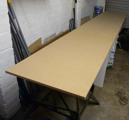
Firstly I needed a flat surface to work on. I put together a 12 foot by 2 foot table with MDF surface. Here it is looking new and shiny before I ruined it will loads of glue and filler -


Secondly I needed to get plans printed off. The two main plans were printed off in 360th scale, which means I simply need to multiply any distance on those plans by five to get 72nd scale. In addition printing off all drawings in full 72nd scale would prove to be really helpful. This was more of a problem as, you've guessed it, most printers on the high street don't print off 15 foot X 7 foot plans. Instead I got 33 separate plans printed off in A0 paper size (841 x 1189 mm) online from www.planprintinguk.com. I then sellotaped the A0 size plans together to provide all the 1/72nd plans I require. Here is one of the plans on the driveway -


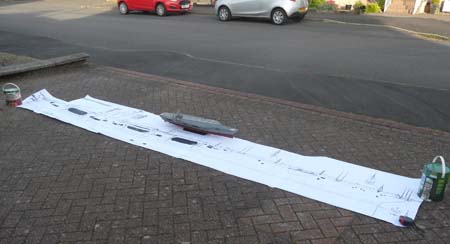
The Nimitz model on top of the plan is in 350th scale (roughly one-fifth of 72nd).

I needed plenty of screengrabs from the movie so I took 370 shots showing all the planes and the ship itself. This was a good excuse to watch the movie again, not that a reason is needed. Have you watched it yet?

When building a wooden model you do, at some stage, have to buy wood. The hull frames are in 6mm thick marine ply whereas the skin will be in 4mm marine ply. Both are purchased in 8 foot by 4 foot sheets. So far I have bought 3 sheets of 6mm and 6 sheets of 4mm marine ply.

I also bought wood for the stringers (stringers go between the frames, with the ply glued to the stringers). The thick ones for the midsection of the hull are 14mm by 28mm so quite strong; I bought 134 feet worth of that and have already run out and have had to buy another 56 feet worth. For the bow and stern I am thinking of using thinner stringers 36mm wide by 6mm deep; so far I have got 65 feet in that size.

Other items on the shopping list were 9mm MDF for the table, 2 big tins of 2-part car body filler, 2 tubs of 2-part wood filler, 4 tubes of wood filler, 7 tubes of bathroom sealant, an electric sander with sandpaper, bandsaw, 100 disposable gloves, 72 20g bottles of Turbo CA glue, 4 large 400ml cans of accelerator, 11 large sheets of plasticard, Colourcoats enamels for the 350th kit, sandpaper, 20mm and 22mm holesaws, 15 steel broom poles, one long steel rule, 6 clamps and 50 sheets of carbon paper. Thankfully I already had a pencil.

The first build task was to draw the hull frames lines onto the 6mm ply. There are 16 frame lines in total, numbering 0 to 15. To draw the hull lines I added carbon paper under the plan and drew the lines with pencil. Here are the sheets on top of 6mm marine ply -


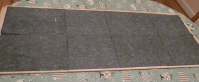
Now here is the plan directly on top -


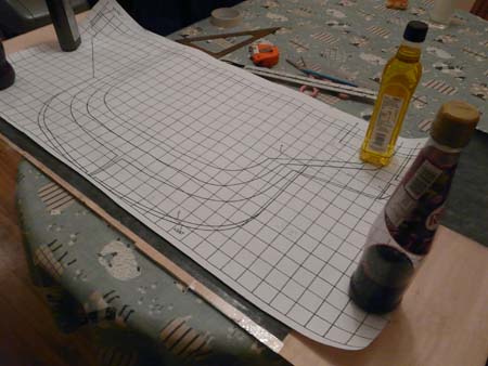
Then it was a case of carefully cutting out the frame lines using my new bandsaw. Here can be seen my test run on a scrap piece of wood -


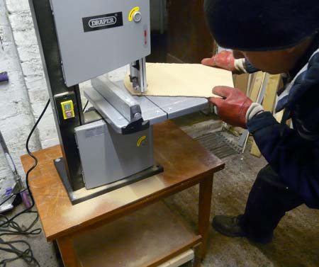
So far I have not needed any emergency procedures due to bandsaw or jigsaw mishaps. All eight fingers and both thumbs remain attached to my hands. However this may change. If you hear reports of an idiot modeller trying to glue a finger back on with Turbo CA glue that will be me. 

Hull frame photos to come tomorrow.

Cheers,

Dougie

Offline Johann Vilthomsen

  • Lieutenant
  • *
  • Posts: 89
« Last Edit: 23 May , 2019, 00:49 by Johann Vilthomsen »

Offline dougie47

  • Administrator
  • *
  • Posts: 758
Hello,

Thanks, Johann, the soundtrack is great too. It is in the tradition of 633 Squadron or the Dam Busters and memorable. I can't think of any modern war movie with a memorable tune.

Here is one of the 15 frames after cutting out by bandsaw -


This shot shows them all stacked together -


This one shows the frames at the bow on top -


I am doing the hull in three main sections:
- firstly the midsection (frames 3 to 10)
- secondly the bow (frames 11 to 14)
- thirdly the stern (frames (0 to 2)

I decided to use metal broom poles for added strength between the frames. These are light, strong and cheap. I am pretty certain nobody has done this before. It is probably unnecessary but as I haven't built a hull before the addition of extra strength can't do any harm (I think). These poles will also help keep the frames in the correct positions while adding the stringers. I needed to get the broom poles in exactly the same location on frames 3 to 10. What I did was clamp the frames together and then drill a 20mm hole where I wanted the pole to go.


The broom poles help me to lift the midsection without any breakages.

Tomorrow I'll post photos of the midsection frames in place. Got to go and paint the first Tomcat now.

Cheers,

Dougie

Offline dougie47

  • Administrator
  • *
  • Posts: 758
Hello,

Here are some more photos of the build. This is the midsection with frames 3 to 10 in place -


The grey steel poles are held in place on the frames by car body filler (P40). The two-part body filler is great for using as an adhesive. You just mix it with the hardener then quickly apply. It is hard to make it look nice and you need to work quickly before it hardens. But it does form a strong bond and holds things in place well. I have used P40 loads when making radio-controlled submarines but strangely enough never as a filler on a car body.

Some of the 14mm by 28mm stringers have been added here but I added more in due course. I cut out 14X28mm gaps in each frame so that the stringer fitted neatly into place on the frame. These were stuck using CA glue and activator. The activator is brilliant stuff as it makes the wood stick together without needing clamps. I then added car body filler around the joins here so that every join becomes really solid.

The next photo shows an area of the hull that has a tight curve -


Here I have added a number of stringers together because I wanted this area of the boat to be really strong.

The next photo (below) shows this area after I added wood filler and sanded with the electric sander -


Now it was time to add the 4mm marine ply skin. The first piece at the top is a bit bigger and does not have much of a curve. I then cut strips for the area with the tight curves -


Then I added 2-part wood filler in the gaps. This is the yellow stuff seen here -


That was then sanded into a nice smooth curve with the electric sander.

More to follow in due course.

Cheers,

Dougie

Offline falo

  • Admiral
  • *
  • Posts: 514
  • Gender: Male
Hi Dougie,

what a project!!!!


Thanks for sharing and regards
falo

Offline dougie47

  • Administrator
  • *
  • Posts: 758
Hi Falo,

Thanks, I may be a bit overambitious with this one. Very steep upskilling required but it has been really fun so far.

A really talented modeller (Gabriel Suranyi) took 19 years to finish a 72nd Enterprise. It is a stunning model with 11,000 tiedowns. The model was so good he was flown in a C-2 as a guest aboard the real Enterprise for two days. Here are some photos -

https://www.carrierbuilders.net/gallery/20070318_USS_Enterprise_1-72/20070318_USS_Enterprise_1-72.htm

Although this is inspiring there is absolutely no way my effort will be anything like Gabriel's masterpiece. I have made a decision not to add loads of detail as I don't fancy taking 19 years to finish it and don't have his level of talent. Plus there is the opportunity cost. If I spend the remainder of my life on this project then it will cost me the opportunity to build other models. There is a 72nd IX coming out this year, for example, and I'd rather build that than add interior lighting to the hangar deck of the Nimitz.

Here are some more images of the 4mm marine ply added to the hull of the midsection. This one shows the strips added prior to the application of wood filler -


This one shows the other side of the hull after filler was added and sanded -


This thing is so big it is essentially a small boat in its own right. Never having built a boat or even a model hull before, I'm a complete novice at this. But even I know that it is preferable to keep the hull from leaking. It will weigh a lot so if it sinks to the bottom of the pond it will ruin my day so much that I'd probably want to end up at the bottom along with the boat. I'm completely making this up but I reckon there are three areas regarding waterproofing. The first is ensuring there are no leaks through the 4mm ply skin. The second is the addition of epoxy over the skin to keep it waterproof. The third is the interior. If I get number one and two right then the interior waterproofing would be unnecessary. However I'm not entirely impressed with my own skills, as evidenced by repeated niggling failures when making and sailing my 96th scale HMS Vanguard sub. So I'm going for the addition of loads of bathroom sealant on the inside of every join on the interior. The sealant is comparatively cheap and added easily with a caulking gun. It might look a bit messy but I've gone for too much sealant rather than too little -


Next up was the hangar decks. The Nimitz class has four huge blastproof steel doors between the hangar deck and the elevators which allow the planes to go up the upper deck. I decided to go with all four doors open, thus permitting a view of the hangar deck. The hangar deck will have no detail whatsoever and I've so far resisted the temptation to add lighting. Two of the doors are on the stern section but two are on the midsection. To cut out the oval shapes from the 4mm ply I started by rolling out one of the 15-foot long plans so I could determine the location of the doors on the hull -


Then I used carbon paper to draw the oval shape upon the ply. Next I cut out the oval shape using my bandsaw. I could have drilled a line of holes and then filed it to shape but due to the size I preferred to use my bandsaw. This required me to cut a line in and out of the oval shape, as can be seen here -


The additional cuts were not a problem as it did not take long to glue the join and add filler to hide the join. Then it was time to add the panel with the oval shape to the hull and tidy it up.

As for the two hangar deck areas, for each area one bulkhead was added at the back and a floor added along the same level as the bottom of the oval. Both the bulkhead and floor are removable so I can gain access to the interior of the hull in order to add ballast (the ballast will be placed under the hangar deck floors).


Last thing for tonight. There is a long panel on the port side which has nine rectangular shaped gaps and four compartments. I needed to add boxes for each of the compartments and these were made out of 4mm ply. Two of the compartments hold lifeboats but I will deal with that later.


That's the initial stage of the midsection done. Since I added lots of strength this 6.5 foot long midsection is quite heavy already.

Cheers,

Dougie

Offline 42rocker

  • Commander
  • *
  • Posts: 312
Good Luck with this interesting project and hope that you keep sharing pics with us. 
 
Later Tim

Offline dougie47

  • Administrator
  • *
  • Posts: 758
Hello,

Here is the next instalment in the Nimitz build. I'm onto the bow now as you can see below. Firstly here are the frames cut out from the plans. The holes are for the metal poles to fit through. And the rectangles cut out around the edge are for the stringers to fit into.


The spacing between the plan frames was too large so I decided to add extra frames in between. I did this by drawing freehand on the carbon paper using the plan frames as a guide. When I cut out the extra frames, I then added them in place between the main frames. Since I have the steel poles to hold them all together, I was able to move the extra frames back and forth until I judged them in the correct place. The following image shows them all in place with CA glue and then car body filler. The wood strip has not been glued yet. It was used to ensure the extra frames were in the correct place (I used a few of these on both sides to determine where the extra frames should be positioned).


Then I added some of the stringers in place on either side. Of note in the image below is the bulbous bow which was built and added early on. I did this by sandwiching together several layers of marine ply, each slightly wider than the next, and then adding wood filler afterwards.


Adding the skin to the very bottom of the bow was next. This was quite difficult as the marine ply decided to be really awkward and not bend easily. The curve is tight at the bottom as you can imagine. In some place I added a deep score (more like a groove) to get the ply to bend. Where this was inadequate I simply cut the wood and added them in a series of strips.


As with the midsection, sealant was added over all the joins in the interior.

What gives the bow its characteristic aircraft carrier look is the near triangular shape. I cut this shape out from the plans, adding a couple of layers (each slightly wider that the other). Then I glued it in place after using a protractor to get the correct angle. The image below shows this piece in place at the bow. Lower down you can see that wood filler has been added over the joins in the ply strips.


Below shows the bow from another angle. Here we can see the wooden strips which spray out behind frame 10. These will reach past frame 9 all the way to reach frame 8 (both 8 and 9 are on the midsection). Much later, when I add the bow section to the midsection, these will be glued in place and the marine ply skin added over the top.


The above image also shows the grey metal poles which will extend back to holes drilled within frame 9 on the midsection. These poles will help to secure the bow section to the midsection in the hope that they don't break apart. If these don't work and the bow breaks off the midsection I imagine I will be somewhat disappointed.

Cheers,

Dougie

Offline dougie47

  • Administrator
  • *
  • Posts: 758
Hello,

Photos below show progress on the bow section -


I now have to improve the bow, particularly the stem area which needs to be thinned.

The big hole isn't because I went mad with a drill. Rather it is for a bow thruster which will be necessary for a hull this big. Although I will have the ability to turn using the propellers (for example, two port motors ahead and two starboard motors in reverse), the addition of a bow thruster will help as well.

Before I fit the bow thruster, I want the four motors, electronic speed controllers (ESCs) and bow thruster all working with the transmitter and receiver. Only once this is done will I be confident to fit the bow thruster. Once the thruster is in place I won't get access to it to fix it or play around with it so I need to get it right first time.

I'll post photos of the electronics another time.

Cheers,

Dougie

Offline Rokket

  • Administrator
  • *
  • Posts: 2,362
  • Gender: Male
  • Submarine Enthusiast
    • AMP - Accurate Model Parts
She is looking great Captain! I'm going to work on a 1:72 bottle of champagne for the launch!
AMP - Accurate Model Parts - http://amp.rokket.biz

Offline Johann Vilthomsen

  • Lieutenant
  • *
  • Posts: 89
 :)
I am impressed by the project you have decided to do.
I am looking to see the future progress in your model.
Strength and Forward!

Offline dougie47

  • Administrator
  • *
  • Posts: 758
Hello,

This will be my last update for a while. I have managed to get a lot done over the summer but time will now be much more limited. Here is where I am at presently.

The bow was shaped more to try to get the curve looking like the real Nimitz class. I also had to reshape the bulbous part at the foot of the bow. I also drilled a few holes near the top of the hull but they have not yet been filed to the oval shape required.


After test fitting the bow onto the midsection, I found the bow was heavy and not being held in place by the metal poles. I therefore added additional metal poles and much longer wooden bars along the top, which I hope will be enough to stop the bow from falling off. I won't be gluing the bow onto the midsection until later because once I do I won't be able to carry or turn it on my own. (it is just test fitted in the image above)

Here is the bow thruster (Raboesch 108-04) connected to a Mtroniks Viper Marine 20 Electronic Speed Controller -


This is the electronics (minus the bow thruster) after testing -


There is a Radiolink T8FB 2.4GHz 8-channel transmitter with two R8EF receivers. The four quite powerful motors are MFA Torpedo 850 Marine Electric Motors. Each of the motors has its own electronic speed controller (ESC). The ESCs I used for the motors are Mtroniks Viper Marine 25. The battery is a Yuasa Yucel 12V 24Ah Sealed Lead Acid Battery which is rather heavy. I was going to use a car battery but I though this might go flat and I hope the Yuasa one will be maintenance free as advertised.

The servo near the bottom isn't suitable for working with 12V and need a lower voltage. I added a UBEC 5V 6V 3A BEC Switch (the green rectangle part in the photo) so that the voltage is suitably reduced.

Talking of voltages, I boobed somewhat and had that familiar burning smell which always seems to occur when I play with electronics. Originally I had each of the motor ESCs going into separate receiver channels. I did not cut any of the red wires which is apparently a mistake. This caused two of the ESCs to blow and the wires to the battery to burn through. After a bit of research I realised my error. Now I have only one of the red wires feeding power into the receiver (I cut all the rest of the red wires). I also have wired it up so that the two port motors are controlled by one receiver channel and the two starboard motors are controlled by a different receiver channel. This will allow the port motors to be controlled by forward movement of one stick and the starboard motor to be controlled by the other stick. Forward on one and reverse on the other will thus allow turning of the stern, meaning that I don't have to rely upon the bow thruster.

The bow thruster has its own ESC, meaning I have five in total.

The electronics all seems to work now, thankfully without any burning smells or drama.

Next up is the stand, which is bigger and heavier than it looks in this image -


This image shows the skeleton of the stern section added to the midsection, which sits on the stand. The stand can be seen on the right hand side and is itself bolted onto a table. The table has wheels on the bottom, making it possible for me to wheel the entire stand and hull along the ground.


As can be seen from the image above, I am using the same method as before, with the grey metal poles between the hull frames and stringers added in place. In the middle is the keel bar which sits centrally. I have build the shell of the area at the stern, as can be seen here -


Detail will be added to this area in due course. The area at the rear is slightly curved, though it cannot be seen in the image.

Cheers,

Dougie

Offline Rokket

  • Administrator
  • *
  • Posts: 2,362
  • Gender: Male
  • Submarine Enthusiast
    • AMP - Accurate Model Parts
Coming along nice. I love your electronics work and description!  :D
AMP - Accurate Model Parts - http://amp.rokket.biz

Offline dougie47

  • Administrator
  • *
  • Posts: 758
Hello all,

Here are a few shots of progress in the Nimitz project.

Firstly this is the boat on its side with the stern areas all closed up. It is getting really awkward in terms of size and weight for me to turn over myself so I am getting used to tuning it on its side now and again.


The stern area has a few details added. I've kept the shelf which should go on the starboard side separate as I would like to paint before adding it.


Next is the starboard side. You can see I've added some of the area here. I used plasticard for the curves as 3mm marine ply is hard to bend.


This is the port side with quite a few areas cut out.


Lastly I added the base for one of the Sea Sparrows near the stern on the port side. I have made this removable with brass rod going into the hull. This is because the hull is getting heavy to handle so having removable parts where possible helps. To make this I added layers of 3mm ply, added wood filler between layers, then sanded to shape. It needed a bit of shaping with the electric sander but got there. I also did the larger Sea Sparrow base near the bow on the starboard side using the same method and it is removable via two bolts.


I've also added the three hangar decks and bulkheads. I'm keeping it basic below decks so no detail will get added but I did need a flat deck as you can see through the four big ovals.

Cheers,

Dougie