Author Topic: VIIC/41 - Schematices drawing  (Read 589030 times)

0 Members and 16 Guests are viewing this topic.

Offline tore

  • Tore
  • *
  • Posts: 2,539
  • Gender: Male
Re: VIIC/41 - Schematices drawing
« Reply #1200 on: 23 Feb , 2014, 12:55 »
Simon.
 The two last end positions are just correct. I wonder about the greasecups though, did you find any pictures or drawings showing same?
Tore

Offline NZSnowman

  • Admiral4
  • *
  • Posts: 2,419
  • Gender: Male
  • U-1308
    • U-1308 - Wikipedia
Re: VIIC/41 - Schematices drawing
« Reply #1201 on: 24 Feb , 2014, 01:29 »
Simon.
 The two last end positions are just correct. I wonder about the greasecups though, did you find any pictures or drawings showing same?
Tore

Below you can see the grease cups :)


Offline tore

  • Tore
  • *
  • Posts: 2,539
  • Gender: Male
Re: VIIC/41 - Schematices drawing
« Reply #1202 on: 24 Feb , 2014, 01:50 »
 Very good, I didn`t remember and had an idea it could be grease nipples. ;D
Tore

Offline NZSnowman

  • Admiral4
  • *
  • Posts: 2,419
  • Gender: Male
  • U-1308
    • U-1308 - Wikipedia
Re: VIIC/41 - Schematices drawing
« Reply #1203 on: 24 Feb , 2014, 01:55 »
Very good, I didn`t remember and had an idea it could be grease nipples.
Tore

 These grease cups seem to be standard throughout the u-boat.

 Tore, was it a shock to the system coming from +30°C to -30°C ;)


Offline tore

  • Tore
  • *
  • Posts: 2,539
  • Gender: Male
Re: VIIC/41 - Schematices drawing
« Reply #1204 on: 24 Feb , 2014, 02:06 »
Simon
You bet, I am still looking for the remote control to turn off the airconditioning ;D Here we have up to 4 meters of snow in the mountains right now and people cannot find their cottages buried in the snow!
Tore

Offline tore

  • Tore
  • *
  • Posts: 2,539
  • Gender: Male
Re: VIIC/41 - Schematices drawing
« Reply #1205 on: 24 Feb , 2014, 07:42 »
Simon
I fully realise there are limits to details however I could not resist adding a few more details to the schnorchel system as you see on the drawing below. The locking pin eyes are obvious. The hydraulic stuffingbox drain is important to prevent oilslick. The inboard drain valve is shown on the photo and the drain ends into the big drainbox on the  forward bulkhead port side of the controlroom. The mast position indicator I have mentioned before. I assume the connection from the hullrod to the mast could be teleflex as fitted on the mechanical indicators for the hydroplanes. The hull transmission is done by a steelrod moving up and down. The cable is indicated on the drawing as heatingcable, I cannot remember that but guess it could be for the radar detectionsystem as well.
Tore

Offline NZSnowman

  • Admiral4
  • *
  • Posts: 2,419
  • Gender: Male
  • U-1308
    • U-1308 - Wikipedia
Re: VIIC/41 - Schematices drawing
« Reply #1206 on: 24 Feb , 2014, 19:50 »
Tore, what do you think the labels read?


Offline NZSnowman

  • Admiral4
  • *
  • Posts: 2,419
  • Gender: Male
  • U-1308
    • U-1308 - Wikipedia
Re: VIIC/41 - Schematices drawing
« Reply #1207 on: 24 Feb , 2014, 21:40 »
The hydraulic stuffing box drain and hydraulic lines added :)

Will add the other things in a few days.


Offline tore

  • Tore
  • *
  • Posts: 2,539
  • Gender: Male
Re: VIIC/41 - Schematices drawing
« Reply #1208 on: 24 Feb , 2014, 23:40 »
Simon.
Valve markings.
The left hydraulic boardvalve marking reads Schnorchelmast senken meaning schnorchelmast lowering. The left valvemarkings reads Druckøl Schnorchelmast heben meaning Pressureoil Schnorchelmast rising.
Tore
« Last Edit: 24 Feb , 2014, 23:43 by tore »

Offline NZSnowman

  • Admiral4
  • *
  • Posts: 2,419
  • Gender: Male
  • U-1308
    • U-1308 - Wikipedia
Re: VIIC/41 - Schematices drawing
« Reply #1209 on: 24 Feb , 2014, 23:59 »
Simon.
Valve markings.
The left hydraulic boardvalve marking reads Schnorchelmast senken meaning schnorchelmast lowering. The left valvemarkings reads Druckøl Schnorchelmast heben meaning Pressureoil Schnorchelmast rising.
Tore

Thanks, I wanted to add the 'naming' plates to the drawing  ;D

Offline tore

  • Tore
  • *
  • Posts: 2,539
  • Gender: Male
Re: VIIC/41 - Schematices drawing
« Reply #1210 on: 25 Feb , 2014, 00:51 »
Simon
If you want to hook up the rest of the schnorchel hydraulic system which is connected to the IMO hyd. motor for the navigation periscope hoist I`ll make a sketch.
Tore

Offline NZSnowman

  • Admiral4
  • *
  • Posts: 2,419
  • Gender: Male
  • U-1308
    • U-1308 - Wikipedia
Re: VIIC/41 - Schematices drawing
« Reply #1211 on: 25 Feb , 2014, 01:01 »
Simon
If you want to hook up the rest of the schnorchel hydraulic system which is connected to the IMO hyd. motor for the navigation periscope hoist I`ll make a sketch.
Tore

I would like to finish the schnorchel hydraulic system. I'm little busy so it maybe a little while before I get to it.

Offline tore

  • Tore
  • *
  • Posts: 2,539
  • Gender: Male
Re: VIIC/41 - Schematices drawing
« Reply #1212 on: 25 Feb , 2014, 02:08 »
Simon.
OK in the meatime I shall try to make a sketch showing the system.
Tore

Offline tore

  • Tore
  • *
  • Posts: 2,539
  • Gender: Male
Re: VIIC/41 - Schematices drawing
« Reply #1213 on: 25 Feb , 2014, 07:55 »
Simon.
Hydraulic system schnorchel.
The system is hooked up to the navigation periscopesystem as indicated on the sketch below. High pressure from the hydraulic system enters the schnorchel maneuvering slide via the stop/ speed throttling valve B. The slide allows the hyd. pressure oil to enter, via the boardvalve, the rising/lowering cylinder on either side as  required. The return oil from the appropriate side of the cylinder passes the boardvalve  to the schnorchel maneuvering slide and then to the stop/ speed throttling valve A before it enters the returnpipe from the periscope winch IMO motor. For some strange reason the B valve housing is painted red and the valve handwheel is removed on the valve shown on the photo from the U 995.
There are several sketches of the schnorchel system, in my opinion the sketch shown is closest to the real thing as on U 995. A and B valves are used to adjust the rising and lowering speed of the mast giving it a smooth homing in both endpositions, whereas the maneuvering slide distributes the pressure- return oil to the appropriate side of the rising/lowering piston.
Tore
« Last Edit: 25 Feb , 2014, 07:59 by tore »

Offline NZSnowman

  • Admiral4
  • *
  • Posts: 2,419
  • Gender: Male
  • U-1308
    • U-1308 - Wikipedia
Re: VIIC/41 - Schematices drawing
« Reply #1214 on: 26 Feb , 2014, 01:47 »
Simon
I fully realise there are limits to details however I could not resist adding a few more details to the schnorchel system as you see on the drawing below. The locking pin eyes are obvious. The hydraulic stuffingbox drain is important to prevent oilslick. The inboard drain valve is shown on the photo and the drain ends into the big drainbox on the  forward bulkhead port side of the controlroom. The mast position indicator I have mentioned before. I assume the connection from the hullrod to the mast could be teleflex as fitted on the mechanical indicators for the hydroplanes. The hull transmission is done by a steelrod moving up and down. The cable is indicated on the drawing as heatingcable, I cannot remember that but guess it could be for the radar detectionsystem as well.
Tore

Spend all afternoon looking for the heating cable and radar detection cable hull openings, could not found them in any photo’s of U-995  :'(
 
Will have it add it to the list of things to check on U-995 when I get there one day.

Offline tore

  • Tore
  • *
  • Posts: 2,539
  • Gender: Male
Re: VIIC/41 - Schematices drawing
« Reply #1215 on: 26 Feb , 2014, 03:56 »
Simon.
I cannot find the cable hull openings either, but for sure the U 995 had a radar detection antenna on top of the schnorchel and some wires had to go into the pressurehull possibly near the sonar/ radioroom.
Tore

Offline NZSnowman

  • Admiral4
  • *
  • Posts: 2,419
  • Gender: Male
  • U-1308
    • U-1308 - Wikipedia
Re: VIIC/41 - Schematices drawing
« Reply #1216 on: 26 Feb , 2014, 20:20 »
Tore, do you have any idea what the horizontal locking mechanism for the schnorchel look like? Does it look like anything below?


Offline NZSnowman

  • Admiral4
  • *
  • Posts: 2,419
  • Gender: Male
  • U-1308
    • U-1308 - Wikipedia
Re: VIIC/41 - Schematices drawing
« Reply #1217 on: 26 Feb , 2014, 23:41 »
Hi Simon!
Sign of life from Africa.
The usual high quality of the drawings,but I have a few remarks. If we return to the original U 995 version having the schnorkel installed in March -April 1945 you see the sketch of same below.
Of course you are aware of the lockingpins in upright and lowered position.
Knowing your interest for details I shall point out the schnorkel position indicator placed in the forward controlroom, see photo and don`t be confused by the red drain cock on the voicepipe. The double indicatorpointers are very much like some pointers on boardvalves.

I have still avoided the lions ;D
Tore

Tore, how does the schnorkel position indicator work and that does the mechanism look like?

Thanks, Simon.

Offline tore

  • Tore
  • *
  • Posts: 2,539
  • Gender: Male
Re: VIIC/41 - Schematices drawing
« Reply #1218 on: 27 Feb , 2014, 00:45 »
Simon.
I cannot remember exactly but I have made a sketch indicating how I believe it is. When the mast is in upright position it needs a firm locking and a screwed pin is used operated by a handwheel in the controlroom. In downright position you just lock it in the horizontal position by a lever in the wardroom. You see photos of both the handwheel and the lever on the sketch below.
Tore

Offline NZSnowman

  • Admiral4
  • *
  • Posts: 2,419
  • Gender: Male
  • U-1308
    • U-1308 - Wikipedia
Re: VIIC/41 - Schematices drawing
« Reply #1219 on: 27 Feb , 2014, 01:18 »
Simon.
I cannot remember exactly but I have made a sketch indicating how I believe it is. When the mast is in upright position it needs a firm locking and a screwed pin is used operated by a handwheel in the controlroom. In downright position you just lock it in the horizontal position by a lever in the wardroom. You see photos of both the handwheel and the lever on the sketch below.
Tore

Thanks, Tore.

I initially thought the "downright position" mechanism would look the way you have sketched it. But if you look at U-766 from 1961 (French submarine Laubie - S610) and U-325 during September 1943 you can see a large flat tab with an opening for a pin.
 
Did you think U-766 and U-325 is an original German deigns and U-995 is an updated Norwegian Navy deign?
 
To me the U-995 deign seen the must simple and better deign.


U-766


U-325

Offline tore

  • Tore
  • *
  • Posts: 2,539
  • Gender: Male
Re: VIIC/41 - Schematices drawing
« Reply #1220 on: 27 Feb , 2014, 02:09 »
Simon.
Again I cannot remember accurately the indicator design, but i made a sketch how I assume it could be.
Tore

Offline tore

  • Tore
  • *
  • Posts: 2,539
  • Gender: Male
Re: VIIC/41 - Schematices drawing
« Reply #1221 on: 27 Feb , 2014, 02:17 »
Simon.
I guess the U 995 lockingpin execution is the original and probably the latest design ( installed March-April 1945), but as you know from previous discussions there are various execution particulary the rodconnection to the upper lockingpin.
Tore

Offline SnakeDoc

  • Admiral
  • *
  • Posts: 536
  • Gender: Male
    • Torpedo Vorhaltrechner Project
Re: VIIC/41 - Schematices drawing
« Reply #1222 on: 27 Feb , 2014, 06:26 »
Hi Gentlemen,


Simon, Schnorchel on Laubie was installed in the middle of 1948. I believe, that it was taken from German supplies, which left in the French naval bases after war, so I believe, it was rather late version. I have attached some pictures of Laubie with Schnorchel. In this time, the shape of the conning tower was changed - from the Turmumbau IV configuration, French removed the after, lower platform.


Your second pictures present U-235 in October 1943, in Germaniaweft (see UAK symbol on the connnig tower). Moreover, U-325 was launched in March 1944, so she could not have installed Schnorchel in November 1943.
Schnorchel installed on U-235 was one of the earliest versions - was lowered and risen by means of cable winch.


--
Regards
Maciek

Offline tore

  • Tore
  • *
  • Posts: 2,539
  • Gender: Male
Re: VIIC/41 - Schematices drawing
« Reply #1223 on: 27 Feb , 2014, 07:51 »
Simon.
Schnorchel lockingpin.
May be the construction require a more detailed explanation. In upright position  the upper part of the rod is threaded and goes into the the lockingpin lowerpart having a bore with internal threads. When the rod rotates it moves the lockingpin up and down. It does not rotates because either the pin is square or in case of a round pin it has a pin in a slot, I don`t know which alt. On the enclosed photo of KNM Kya ex U 926 it seems that the lockingpin is located inside the homing fork, contrary to the German drawing.
Tore

Offline tore

  • Tore
  • *
  • Posts: 2,539
  • Gender: Male
Re: VIIC/41 - Schematices drawing
« Reply #1224 on: 27 Feb , 2014, 08:14 »
Simon.
Schnorchel position indicator.
I did not like my previous assumption so much as I would assume a rotating rod would be more appropriate. In this case if you follow the German practise you could end up with a solution  indicated on the drawing below. The indicator is pretty much the same as the indicator on some important valves, the double pointer on the travellingnut prevent same to rotate hence the pointer goes up and down according to the mastposition. I cannot guaranty that this solution is the original execution at this point remains  an intelligent guessing as so many times before.
Tore

Offline tore

  • Tore
  • *
  • Posts: 2,539
  • Gender: Male
Re: VIIC/41 - Schematices drawing
« Reply #1225 on: 27 Feb , 2014, 08:25 »
Simon.
Locking pin downright postion.
If you look at the handlearm and guide in the wardroom you shall notice there are holes drilled in the handle and the guide, they are holes for a securingpin to lock the handle in position.

Offline NZSnowman

  • Admiral4
  • *
  • Posts: 2,419
  • Gender: Male
  • U-1308
    • U-1308 - Wikipedia
Re: VIIC/41 - Schematices drawing
« Reply #1226 on: 27 Feb , 2014, 12:19 »
Simon.
Schnorchel position indicator.
I did not like my previous assumption so much as I would assume a rotating rod would be more appropriate. In this case if you follow the German practise you could end up with a solution  indicated on the drawing below. The indicator is pretty much the same as the indicator on some important valves, the double pointer on the travellingnut prevent same to rotate hence the pointer goes up and down according to the mastposition. I cannot guaranty that this solution is the original execution at this point remains  an intelligent guessing as so many times before.
Tore

Tore, the green spot is the location for the hull opening for the Schnorchel position indicator.


Offline tore

  • Tore
  • *
  • Posts: 2,539
  • Gender: Male
Re: VIIC/41 - Schematices drawing
« Reply #1227 on: 27 Feb , 2014, 12:28 »
Simon.
Final solution to the upright lockingpin.
Having studied the U 968 photo I believe I have found the final design. The homingfork has the upper hole and it is square, the lower fixingpoint is bolted to the common supportplate. The working is pretty much as explained before and the pin is square which prevent it from turning with the threaded rodend. I have tried to make a sketch referring to the photo.
Tore

Offline NZSnowman

  • Admiral4
  • *
  • Posts: 2,419
  • Gender: Male
  • U-1308
    • U-1308 - Wikipedia
Re: VIIC/41 - Schematices drawing
« Reply #1228 on: 27 Feb , 2014, 12:41 »
Simon.
I guess the U 995 lockingpin execution is the original and probably the latest design ( installed March-April 1945), but as you know from previous discussions there are various execution particulary the rodconnection to the upper lockingpin.
Tore

I just found two more photo's in Vom Original zum Modell, Uboottyp VII C with the "large flat tab" with an opening for a pin


Offline NZSnowman

  • Admiral4
  • *
  • Posts: 2,419
  • Gender: Male
  • U-1308
    • U-1308 - Wikipedia
Re: VIIC/41 - Schematices drawing
« Reply #1229 on: 27 Feb , 2014, 12:47 »
Simon.
Schnorchel position indicator.
I did not like my previous assumption so much as I would assume a rotating rod would be more appropriate. In this case if you follow the German practise you could end up with a solution  indicated on the drawing below. The indicator is pretty much the same as the indicator on some important valves, the double pointer on the travellingnut prevent same to rotate hence the pointer goes up and down according to the mastposition. I cannot guaranty that this solution is the original execution at this point remains  an intelligent guessing as so many times before.
Tore

Tore, here the solution for the Schnorchel position indicator on the Type IX from Vom Original zum Modell, Uboottyp IX C


Offline NZSnowman

  • Admiral4
  • *
  • Posts: 2,419
  • Gender: Male
  • U-1308
    • U-1308 - Wikipedia
Re: VIIC/41 - Schematices drawing
« Reply #1230 on: 27 Feb , 2014, 15:33 »
Hi Tore

Was thinking about different ways to gear the Schnorchel position indicator. What do you think about this idea?


Offline tore

  • Tore
  • *
  • Posts: 2,539
  • Gender: Male
Re: VIIC/41 - Schematices drawing
« Reply #1231 on: 28 Feb , 2014, 00:24 »
Simon.
It works but I am afraid it is an expensive way of doing it and requires complicated milling. At the end of WW2 I believe the germans would go for a simpler solution. I have been pondering upon this detail further and further studies of the bad photo of the internal indicator rod does not reveal any threads which is needed for a travelling pointernut. Thus I assume the rotating rod theory even if would be a technical good solution might be abandoned. :-[ Back to the drawingboard. I am reintroducing my first idea, teleflex, as used for the mechanical indicators of the hydroplanes. It is relatively simple and cheap. On the sketch below you see it is some strange bends which might support the theory. At the  rod connectingpoint it got to be a 90 degrees angleguide though in order to have a vertical pull/ push movement of the rod. These guides are standard teleflex equipment. By studying the teleflex transmission of the hydroplane indicators we might find a possible solution for the relative simple schnorchel indicator. ;)
Tore

Offline NZSnowman

  • Admiral4
  • *
  • Posts: 2,419
  • Gender: Male
  • U-1308
    • U-1308 - Wikipedia
Re: VIIC/41 - Schematices drawing
« Reply #1232 on: 28 Feb , 2014, 01:09 »
Here are all the different version of the 3.7cm Flak M42U found on Type VIIC's

3.7cm Flak M42U

The 3.7cm Flak M42U was the marine version of the 3.7cm Flak used by the Kriegsmarine on Type VII and Type IX U-boats. The improvement was base on the earlier 3.7cm Flak SK C/30 developed by Rheinmetall. The 3.7cm Flak M42U used several types of mounts and entered service in autumn 1943.

LM 42U Mount
The LM 42U mount was developed specifically for the 3.7cm Flak M42U. It was man by a 3 man crew, with a fourth man, the loader.

LM 43U Mount
The LM 43U mount was the final deign of mount used on U-boats. It further improvement on the LM 42U. The LM 43U was only known to be installed on three U-boats (U-1171, U-1305 and U-1306).

DLM 42U Mount
The twin mount was base on the  design, in which the 3.7cm Flak M42U guns were mounted side by side.


Fig. 1. A Single 3.7cm Flak M42U gun on the LM 42U mount.


Fig. 2. A Single 3.7cm Flak M42U gun on the LM 43U mount.


Fig. 3. A Twin 3.7cm Flak M42U guns on the DLM 42U mount.

Offline Rokket

  • Administrator
  • *
  • Posts: 2,362
  • Gender: Male
  • Submarine Enthusiast
    • AMP - Accurate Model Parts
Re: VIIC/41 - Schematices drawing
« Reply #1233 on: 28 Feb , 2014, 16:07 »
I don't know anything about this specifically, so I can only comment in general, which might be useless!

Some related info. The US Gatos were well engineered. Modern volunteers rebuilt a periscope on the Cobia a few years ago. They couldn't understand some of the design and thought it was over-engineered. UNTIL they went to put it back together, and all the awkward, impossible-ness of the procedure was made easy by the design! The volunteers went "AH! these 1930s + 40s guys knew what they were doing!"

The other bit: it's almost impossible to second guess the past. Why would people do something in a certain way? "of course they wouldn't!" we say, but then we don't have their world view. We don't cover up in the heat, but the people of the 1600s seem to have (from paintings and writings). They thought layers kept them cool, and that the air was filled with disease. Different logic. So on one hand these guys might not have put effort into complex gearing, but on the other, it might have seemed perfectly natural, even with limited resources. After all, Germany was putting  lot of effort into almost science fiction weapons, even though it was too late...

Just some thoughts.
AMP - Accurate Model Parts - http://amp.rokket.biz

Offline tore

  • Tore
  • *
  • Posts: 2,539
  • Gender: Male
Re: VIIC/41 - Schematices drawing
« Reply #1234 on: 01 Mar , 2014, 00:31 »
Very wise words. When we try to figure out why a VIIC was equipped like this or that, we often forget the situation in Germany the last years of WW2. The VIIC technology is pretty much from the 1920 and 1930 years. In contradiction to f.i. the RN which in the 30 ties had their subs equipped with telemotor operated vents and hydroplanes, the germans still used mechanical transmission, rods and links.The VIIC was the workhorse based on wellproven prewar technology. I remember in 1943-1944 as a boy in an occupied country, the  germans where desperate in getting rawmaterial, they confiscated all our copper- and nickelcoins, all the brass items on subwaycars,trams and railwaycars like handles, supportrods, ashtrays etc. The brass and nickel items were remelted as a substitute we got steel and zinc coins, wooden supportrods etc. After Stalingrad, end 42 beginning 43, the families had to supply the German military with their private rubberboots, blankets and rucksacs. In the years of the schnorchel installation, the shipyards and factories were heavily bombed and destroyed, making it pretty difficult to get the proper parts and material for the conversion. It is easy to forget the prevailing circumstances when you wonder why the German did it the way they did and why they did not use copper, bronze and brass in the piping.
Tore 

Offline tore

  • Tore
  • *
  • Posts: 2,539
  • Gender: Male
Re: VIIC/41 - Schematices drawing
« Reply #1235 on: 01 Mar , 2014, 08:01 »
Simon.
I have spent some time studying the possible solution to the Schnorchelmast indicator. The drawings available does not give much information, but they indicates rodlink transmission even if some are overdimensioned. I have checked the indicator for the ballast vents and the Kingstons on U 995, to my astonishment you could not see any threads on indicator spindles, I guess they might be heavily painted so the threads do not show up on a bad photo.  However I guess for the indicator travel shown on the photo a direct 90 degrees mast movement at the rooth of the mast  hardly gives a direct link transmission sufficient turning of  the spindle to create  such travel.If we stick to the rotating theory, we have to amplify the turns from 90 degrees to at least 2 or 3 x 360 degrees. At a direct pull push movement it would be possible to obtain the adequat movement I guess. These are just some thougths around the problems to be solved.  May be we should wait and see if some better documentation pops up before ending up with the final solution.
Tore
« Last Edit: 01 Mar , 2014, 09:17 by tore »

Offline NZSnowman

  • Admiral4
  • *
  • Posts: 2,419
  • Gender: Male
  • U-1308
    • U-1308 - Wikipedia
Re: VIIC/41 - Schematices drawing
« Reply #1236 on: 02 Mar , 2014, 00:16 »
Hi Tore

I was taking another look at the Schnorchel mast indicator and I noted that a ¼ of the circumference of the Schnorchel pipe was the same amount of movement for the indicated bar (light blue) so this made me think:
 
When the Schnorchel mast is down the Green bar (which is Attached to the Schnorchel pipe) is moved forward, pushing a cable (purple) forward that forces the indicated arrow down.
When the Schnorchel mast is up, the green bar is pull back, pulling the cable (purple) back and pulling the indicated arrow back up.
 
The cable (purple) would be fed into a bend of a pipe to stop the cable creasing.

What do you think?


Down


Up
« Last Edit: 02 Mar , 2014, 00:18 by NZSnowman »

Offline tore

  • Tore
  • *
  • Posts: 2,539
  • Gender: Male
Re: VIIC/41 - Schematices drawing
« Reply #1237 on: 02 Mar , 2014, 02:15 »
Simon.
This was my first idea ( teleflex) as well, and I believe you could even get the guide and other components as a standard from teleflex as used on the hydroplanes mechanical indicators. There is one problem as the teleflex cable runs in a sleeve which is not pressure / waterthight it creates a problem for the pressurehull stuffingbox and the indicator rod has to end outside the pressurehull to overcome this problem. By that you introduce  a higher resistance which I am not sure a teleflex pushmovement can overcome.
Tore

Offline Rokket

  • Administrator
  • *
  • Posts: 2,362
  • Gender: Male
  • Submarine Enthusiast
    • AMP - Accurate Model Parts
Re: VIIC/41 - Schematices drawing
« Reply #1238 on: 03 Mar , 2014, 04:54 »
Tore - wow, I wish I could take you out for a beer! You lived it. Thanks so much for sharing with us!
AMP - Accurate Model Parts - http://amp.rokket.biz

Offline tore

  • Tore
  • *
  • Posts: 2,539
  • Gender: Male
Re: VIIC/41 - Schematices drawing
« Reply #1239 on: 03 Mar , 2014, 23:32 »
Simon.
Schnorchel mast indicator.
I guess we should find the simplest solution which would be pull/push rods. Below I have indicated such a system. I have estimated the vertical movement of the indicator to be some 15-20 cm (I am not sure), this would require the connection point to the mast to be close to the root of the mast as the rodlink should be as straight as possible. Thus the hullpassage would be fairly close to the fulcrum of the mast. Unfortunately this is slightly different from what is indicated on the systemsketch however there are several other details on the sketch which are not correct as well. On the U 995 photo the indicator rod enters the hull (controlroom) in the middle between frame 60 and 61 as far as I can see and I don`t know how this matches the position of the fulcrum, you have probably some details on this. This is my best assumption for you drawing of the indicator right now. ;)
Tore
« Last Edit: 03 Mar , 2014, 23:39 by tore »

Offline falo

  • Admiral
  • *
  • Posts: 514
  • Gender: Male
Re: VIIC/41 - Schematices drawing
« Reply #1240 on: 03 Mar , 2014, 23:50 »

Don't know if this technical drawing is already on your HD. Grabbed this drawing from an unknown internet site years ago. Just remembering that the attached snorkel-drawings are for a type nine boat.

Falo

Offline tore

  • Tore
  • *
  • Posts: 2,539
  • Gender: Male
Re: VIIC/41 - Schematices drawing
« Reply #1241 on: 04 Mar , 2014, 00:13 »
Falo.
It is a very good drawing, but as you say it is showing the IX system which is different from the VIICs. Main difference are the cranks downwards and the indicator (rotating) and possibly the tranmission are different .
Tore

Offline NZSnowman

  • Admiral4
  • *
  • Posts: 2,419
  • Gender: Male
  • U-1308
    • U-1308 - Wikipedia
Re: VIIC/41 - Schematices drawing
« Reply #1242 on: 04 Mar , 2014, 00:43 »
Simon.
Schnorchel mast indicator.
I guess we should find the simplest solution which would be pull/push rods. Below I have indicated such a system. I have estimated the vertical movement of the indicator to be some 15-20 cm (I am not sure), this would require the connection point to the mast to be close to the root of the mast as the rodlink should be as straight as possible. Thus the hullpassage would be fairly close to the fulcrum of the mast. Unfortunately this is slightly different from what is indicated on the systemsketch however there are several other details on the sketch which are not correct as well. On the U 995 photo the indicator rod enters the hull (controlroom) in the middle between frame 60 and 61 as far as I can see and I don`t know how this matches the position of the fulcrum, you have probably some details on this. This is my best assumption for you drawing of the indicator right now. ;)
Tore

Tore, the pressure hull opening for the Schnorchel mast indicator is a long way from the Schnorchel.

The pressure hull opening for the Schnorchel mast indicator is 645 mm forward of the fulcrum point and 500 mm inboard from the central line of the Schnorchel mast.

Offline tore

  • Tore
  • *
  • Posts: 2,539
  • Gender: Male
Re: VIIC/41 - Schematices drawing
« Reply #1243 on: 04 Mar , 2014, 01:38 »
Simon, back to the drawingboard ;D
Tore

Offline NZSnowman

  • Admiral4
  • *
  • Posts: 2,419
  • Gender: Male
  • U-1308
    • U-1308 - Wikipedia
Re: VIIC/41 - Schematices drawing
« Reply #1244 on: 04 Mar , 2014, 01:45 »
Simon, back to the drawingboard ;D
Tore

Is it not a bad thing, as it mean that there a lot more room for the Schnorchel mast indicator mechanical under the wooden deck  ;)

Offline NZSnowman

  • Admiral4
  • *
  • Posts: 2,419
  • Gender: Male
  • U-1308
    • U-1308 - Wikipedia
Re: VIIC/41 - Schematices drawing
« Reply #1245 on: 04 Mar , 2014, 12:16 »
Tore, the green spot is the location for the hull opening for the Schnorchel position indicator.


Was looking at something other this morning and noted the plan of the 'Bold' it got many of the mechanical system needed for the Schnorchel position indicator, it must give us a idea  :)
http://www.u-historia.com/uhistoria/tecnico/visitaguiada/lanzasenyuelos/lanzasenyuelos.htm

Offline NZSnowman

  • Admiral4
  • *
  • Posts: 2,419
  • Gender: Male
  • U-1308
    • U-1308 - Wikipedia
Re: VIIC/41 - Schematices drawing
« Reply #1246 on: 09 Mar , 2014, 22:48 »
Update on the LM 43U mount.

Now also known from U-249 and U-1028.


Here are all the different version of the 3.7cm Flak M42U found on Type VIIC's

3.7cm Flak M42U

The 3.7cm Flak M42U was the marine version of the 3.7cm Flak used by the Kriegsmarine on Type VII and Type IX U-boats. The improvement was base on the earlier 3.7cm Flak SK C/30 developed by Rheinmetall. The 3.7cm Flak M42U used several types of mounts and entered service in autumn 1943.

LM 42U Mount
The LM 42U mount was developed specifically for the 3.7cm Flak M42U. It was man by a 3 man crew, with a fourth man, the loader.

LM 43U Mount
The LM 43U mount was the final deign of mount used on U-boats. It further improvement on the LM 42U. The LM 43U was only known to be installed on three U-boats (U-1171, U-1305 and U-1306).

DLM 42U Mount
The twin mount was base on the  design, in which the 3.7cm Flak M42U guns were mounted side by side.


Fig. 1. A Single 3.7cm Flak M42U gun on the LM 42U mount.


Fig. 2. A Single 3.7cm Flak M42U gun on the LM 43U mount.


Fig. 3. A Twin 3.7cm Flak M42U guns on the DLM 42U mount.

Offline Capt Kremin

  • Commander
  • *
  • Posts: 273
  • Gender: Male
Re: VIIC/41 - Schematices drawing
« Reply #1247 on: 24 Mar , 2014, 04:22 »
Hi NZSnowman
 
I took these last month on the U 534 of her M43U DLM42U, hope they help, if you would like the full sized images, pm me with an email addy.
 
1 of 3
 
Regards
 
Jon
"Here's Peter Jason Quill, He's also called Starlord",
"Who calls him that?",
"Himself Mostly".

Offline Capt Kremin

  • Commander
  • *
  • Posts: 273
  • Gender: Male
Re: VIIC/41 - Schematices drawing
« Reply #1248 on: 24 Mar , 2014, 04:35 »
Hi All
 
Can't count, 9 photos in all
 
2 of 5
 
Regards
 
Jon
"Here's Peter Jason Quill, He's also called Starlord",
"Who calls him that?",
"Himself Mostly".

Offline Capt Kremin

  • Commander
  • *
  • Posts: 273
  • Gender: Male
Re: VIIC/41 - Schematices drawing
« Reply #1249 on: 24 Mar , 2014, 04:40 »
Hi All
 
Can't count, 9 photos in all
 
3 of 5
 
Regards
 
Jon
"Here's Peter Jason Quill, He's also called Starlord",
"Who calls him that?",
"Himself Mostly".

Offline Capt Kremin

  • Commander
  • *
  • Posts: 273
  • Gender: Male
Re: VIIC/41 - Schematices drawing
« Reply #1250 on: 24 Mar , 2014, 04:42 »
Hi All
 
Can't count, 9 photos in all
 
4 of 5
 
Regards
 
Jon
"Here's Peter Jason Quill, He's also called Starlord",
"Who calls him that?",
"Himself Mostly".

Offline Capt Kremin

  • Commander
  • *
  • Posts: 273
  • Gender: Male
Re: VIIC/41 - Schematices drawing
« Reply #1251 on: 24 Mar , 2014, 04:46 »
Hi All
 
Last picture,
 
and finally
 
NZSnowman
Dougie suggested I show you this last pic, hope you're sitting down, this is how not to restore the deck of a type IXC40 courtesy of Mersey Travel
 
Regards
 
Jon
"Here's Peter Jason Quill, He's also called Starlord",
"Who calls him that?",
"Himself Mostly".

Offline NZSnowman

  • Admiral4
  • *
  • Posts: 2,419
  • Gender: Male
  • U-1308
    • U-1308 - Wikipedia
Re: VIIC/41 - Schematices drawing
« Reply #1252 on: 24 Mar , 2014, 10:17 »
Hi All
 
Last picture,
 
and finally
 
NZSnowman
Dougie suggested I show you this last pic, hope you're sitting down, this is how not to restore the deck of a type IXC40 courtesy of Mersey Travel
 
Regards
 
Jon

Thanks, they are great  :) :)

I can see lots of new details I can add to my drawings  :)

Thank again!

Offline Capt Kremin

  • Commander
  • *
  • Posts: 273
  • Gender: Male
Re: VIIC/41 - Schematices drawing
« Reply #1253 on: 25 Mar , 2014, 07:06 »
Hi NZSnowman
 
No problems
 
In case you are wondering about the odd angles, the pictures were taken from a camera attached to a carbon fibre telescopic flagpole.  :)
 
Regards
 
Jon
"Here's Peter Jason Quill, He's also called Starlord",
"Who calls him that?",
"Himself Mostly".

Offline NZSnowman

  • Admiral4
  • *
  • Posts: 2,419
  • Gender: Male
  • U-1308
    • U-1308 - Wikipedia
Re: VIIC/41 - Schematices drawing
« Reply #1254 on: 25 Mar , 2014, 19:52 »
Base on Jon photo's I noted my drawing of the DLM 42U mount did not match the photo’s. So I recheck my photo's and the drawings in German Naval Guns 1939-1945 by Miroslaw Skwiot.
 
The drawing on page 341 is incorrect! The two drawing of the side views are of a LM 42U mount not the DLM 42U mount! :o

New drawing is base on photo’s of the DLM 42U mount.

« Last Edit: 25 Mar , 2014, 19:58 by NZSnowman »

Offline NZSnowman

  • Admiral4
  • *
  • Posts: 2,419
  • Gender: Male
  • U-1308
    • U-1308 - Wikipedia
Re: VIIC/41 - Schematices drawing
« Reply #1255 on: 26 Mar , 2014, 14:37 »
Simon
I fully realise there are limits to details however I could not resist adding a few more details to the schnorchel system as you see on the drawing below. The locking pin eyes are obvious. The hydraulic stuffingbox drain is important to prevent oilslick. The inboard drain valve is shown on the photo and the drain ends into the big drainbox on the  forward bulkhead port side of the controlroom. The mast position indicator I have mentioned before. I assume the connection from the hullrod to the mast could be teleflex as fitted on the mechanical indicators for the hydroplanes. The hull transmission is done by a steelrod moving up and down. The cable is indicated on the drawing as heatingcable, I cannot remember that but guess it could be for the radar detectionsystem as well.
Tore

Spend all afternoon looking for the heating cable and radar detection cable hull openings, could not found them in any photo’s of U-995  :'(
 
Will have it add it to the list of things to check on U-995 when I get there one day.

Simon.
I cannot find the cable hull openings either, but for sure the U 995 had a radar detection antenna on top of the schnorchel and some wires had to go into the pressurehull possibly near the sonar/ radioroom.
Tore

Thanks to Falo photo's I think I have location the heating cable and radar detection cable hull openings in U-995 :)

Base on DSC_0127.JPG photo, http://models.rokket.biz/index.php?topic=1150.msg15066#msg15066 you can see a Pressure Hull opening in the top right of the photo. I initial thought the black colour on the pipe was a colour code, but from Falo high-res photo (below) you can see it unpainted electrical braided cable :)

Tore, what do you think, also what do you think about other opening in the top left of the photo?


Offline tore

  • Tore
  • *
  • Posts: 2,539
  • Gender: Male
Re: VIIC/41 - Schematices drawing
« Reply #1256 on: 27 Mar , 2014, 02:46 »
Simon.
I agree this is probably the  radarwarning cable going towards the sonar radio rooms. As to the red painted pressurehull opening it looks like a cable opening as well. Could that be the removed heatingcable?.
Tore

Offline NZSnowman

  • Admiral4
  • *
  • Posts: 2,419
  • Gender: Male
  • U-1308
    • U-1308 - Wikipedia
Re: VIIC/41 - Schematices drawing
« Reply #1257 on: 27 Mar , 2014, 13:43 »
Simon.
I agree this is probably the  radarwarning cable going towards the sonar radio rooms. As to the red painted pressurehull opening it looks like a cable opening as well. Could that be the removed heatingcable?.
Tore

I was thinking the same thing, the other opening was the heating cable, but I was also wondering would the German's run both the heating and radar detection cables together through  the same opening?

Offline tore

  • Tore
  • *
  • Posts: 2,539
  • Gender: Male
Re: VIIC/41 - Schematices drawing
« Reply #1258 on: 27 Mar , 2014, 15:18 »
Simon.
I don`t think you can put the two cables through the same pressure hull stuffingbox.
Tore

Offline NZSnowman

  • Admiral4
  • *
  • Posts: 2,419
  • Gender: Male
  • U-1308
    • U-1308 - Wikipedia
Re: VIIC/41 - Schematices drawing
« Reply #1259 on: 28 Mar , 2014, 14:03 »
Tore, I have estimated the two pressure hull openings. The heating cable is aft of the Schnorchel hinge, and the radar detection cable forward of Schnorchel hinge next to the Schnorchel Hydraulic Stuffingbox Drain.


Offline NZSnowman

  • Admiral4
  • *
  • Posts: 2,419
  • Gender: Male
  • U-1308
    • U-1308 - Wikipedia
Re: VIIC/41 - Schematices drawing
« Reply #1260 on: 28 Mar , 2014, 15:07 »

Fig. 1. The outside view of the Balcongerät installed on U-995 sometime in the 1970's by the Royal Norwegian Navy.


Fig. 2. The inside view of the Balcongerät installed on U-995 sometime in the 1970's by the Royal Norwegian Navy.


Fig. 3. The outside view of the German design of Balcongerät installed on Type VIIC's (U-778, U-997, U-1021, U-1105 & U-1308).


Fig. 4. The inside view of the German design of Balcongerät installed on Type VIIC's.
« Last Edit: 28 Mar , 2014, 15:10 by NZSnowman »

Offline tore

  • Tore
  • *
  • Posts: 2,539
  • Gender: Male
Re: VIIC/41 - Schematices drawing
« Reply #1261 on: 28 Mar , 2014, 15:38 »
Simon.
Some time in  1960 the Royal Norwegian Navy had plans for modernising the VIIC class however only one boat was modernised KNM Kya ex U 926 as the project was abandoned in view of a newbuilding programme. The boat should be equipped with a telescopic schnorchelmast,  a "sail" and a new balkongeraet. I have only a drawing of same as shown below.
Tore

Offline NZSnowman

  • Admiral4
  • *
  • Posts: 2,419
  • Gender: Male
  • U-1308
    • U-1308 - Wikipedia
Re: VIIC/41 - Schematices drawing
« Reply #1262 on: 28 Mar , 2014, 15:47 »
U-995 Balcongerät was removed sometime between 4 November 1971 and 13 March 1972.
 
Tore, what happen to KNM Kya?

Offline tore

  • Tore
  • *
  • Posts: 2,539
  • Gender: Male
Re: VIIC/41 - Schematices drawing
« Reply #1263 on: 28 Mar , 2014, 15:52 »
Simon, she was the last VIIC I had and she was scrapped around mid 1960.
Tore

Offline NZSnowman

  • Admiral4
  • *
  • Posts: 2,419
  • Gender: Male
  • U-1308
    • U-1308 - Wikipedia
Re: VIIC/41 - Schematices drawing
« Reply #1264 on: 28 Mar , 2014, 15:59 »
...she was scrapped around mid 1960.

 :'( :'(

Was there must different in the piping in the engine rooms between the two boats, Tore?

Offline tore

  • Tore
  • *
  • Posts: 2,539
  • Gender: Male
Re: VIIC/41 - Schematices drawing
« Reply #1265 on: 28 Mar , 2014, 16:11 »
Simon.
There was some difference but not very much, as far as I remember the biggest difference was on KNM Kinn ex U 1202. I cannot today remember the details of the differences but I am pretty sure non of them had a luboil purifier.  As you know the U 926 and U 1202 were both VIICs only U995 was VIIC/41.
Tore

Offline NZSnowman

  • Admiral4
  • *
  • Posts: 2,419
  • Gender: Male
  • U-1308
    • U-1308 - Wikipedia
Re: VIIC/41 - Schematices drawing
« Reply #1266 on: 29 Mar , 2014, 12:35 »
Tore, what do you think of my cable alignment? (Blue = radar detection cable, red = heating cable)


Offline tore

  • Tore
  • *
  • Posts: 2,539
  • Gender: Male
Re: VIIC/41 - Schematices drawing
« Reply #1267 on: 30 Mar , 2014, 00:44 »
Simon.
I Guess this is OK. May be we should look for the potential cablebox for the heatingcable in the port forward area. The radar detectioncable would possibly go to the sonarroom.
Tore

Offline falo

  • Admiral
  • *
  • Posts: 514
  • Gender: Male
Re: VIIC/41 - Schematices drawing
« Reply #1268 on: 14 Apr , 2014, 01:40 »
Hi Snowman,


here we go with the Alberich coated XXIII boat(s). According to the text there were only two XXIII-Boats coated with the tiles: U-4704 and U-4708.


Regards
Falo

Offline NZSnowman

  • Admiral4
  • *
  • Posts: 2,419
  • Gender: Male
  • U-1308
    • U-1308 - Wikipedia
Re: VIIC/41 - Schematices drawing
« Reply #1269 on: 14 Apr , 2014, 01:53 »
Hi Snowman,


here we go with the Alberich coated XXIII boat(s). According to the text there were only two XXIII-Boats coated with the tiles: U-4704 and U-4708.


Regards
Falo

Thanks  :)

I have read that only a three Type XXIII boats were coated with Alberich (U-4704, U-4707 & U-4708). The German planed to coat all the Type XXIII's and XXI's. I believe no Type XXI's got coated with Alberich.


Offline falo

  • Admiral
  • *
  • Posts: 514
  • Gender: Male
Re: VIIC/41 - Schematices drawing
« Reply #1270 on: 14 Apr , 2014, 09:09 »
Snowmann,


according to the text (translated from german to english), there existed plans to coat one-third from total 185 XXIII-boats to be completed til the end of 1945.


Regards
Falo

Offline SG

  • Admiral
  • *
  • Posts: 661
    • https://3xblackcats.wordpress.com/
Re: VIIC/41 - Schematices drawing
« Reply #1271 on: 14 Apr , 2014, 09:38 »
Simon, Awesome work w the balcongerat, as usual
Congrats!

Offline falo

  • Admiral
  • *
  • Posts: 514
  • Gender: Male
Re: VIIC/41 - Schematices drawing
« Reply #1272 on: 22 May , 2014, 07:50 »
Hi Snowman,

just a (probably redundant) question according to alberich boats with mounted „Balkon-Geraet“ (please read the text below). If the „Balkon-Geraet“ was installed, did the Alberich boats also had mounted the GHG (24 hydrophones) around the hydroplanes resp. on the side of the bow? IMO that would be done twice.

Thanks in advance and regards
Falo

Gruppenhorchgerat (GHG)
The standard U-boat hydrophone, the GHG (Group Listening Apparatus) was installed in U-boats from 1935 onwards. It consisted of two sets of hydrophones mounted on each side of the bows, covering two arcs of 140 degrees on the sides of the U-boat. Because the hydrophones could not be rotated, the triangulation was most effective with sound sources coming from the sides, with deteriorating accuracy as the source moved to the front or rear of the boat. Consisting of 24 hydrophones, the GHG could pick up lone vessels up to 20 kilometers and convoys up to 100 kilometers away.

Balkon Geraet
The Balkon Great (Balcony Apparatus) was an improved version of GHG. Where the previous had 24 hydrophones, the Balkon had 48 hydrophones and improved electronics, which enabled more accurate readings to be taken. The Balkon was standard on the Type XXI and was also fitted to several Type VIIs.

Offline NZSnowman

  • Admiral4
  • *
  • Posts: 2,419
  • Gender: Male
  • U-1308
    • U-1308 - Wikipedia
Re: VIIC/41 - Schematices drawing
« Reply #1273 on: 22 May , 2014, 15:22 »
Hi Snowman,

just a (probably redundant) question according to alberich boats with mounted „Balkon-Geraet“ (please read the text below). If the „Balkon-Geraet“ was installed, did the Alberich boats also had mounted the GHG (24 hydrophones) around the hydroplanes resp. on the side of the bow? IMO that would be done twice.

Thanks in advance and regards
Falo

Gruppenhorchgerat (GHG)
The standard U-boat hydrophone, the GHG (Group Listening Apparatus) was installed in U-boats from 1935 onwards. It consisted of two sets of hydrophones mounted on each side of the bows, covering two arcs of 140 degrees on the sides of the U-boat. Because the hydrophones could not be rotated, the triangulation was most effective with sound sources coming from the sides, with deteriorating accuracy as the source moved to the front or rear of the boat. Consisting of 24 hydrophones, the GHG could pick up lone vessels up to 20 kilometers and convoys up to 100 kilometers away.

Balkon Geraet
The Balkon Great (Balcony Apparatus) was an improved version of GHG. Where the previous had 24 hydrophones, the Balkon had 48 hydrophones and improved electronics, which enabled more accurate readings to be taken. The Balkon was standard on the Type XXI and was also fitted to several Type VIIs.

I never see any information on this, if the GHG was were remove from Balkon-Geraet boats.
 
I believe, as the Balkon-Geraet was an add-on for Type VIIC’s that the GHG was not removed but was just disconnect.

I believe that perhaps the only Type VII’s that was not install with a GHG system could be U-1308. U-1308 was the last Type VII’s to be build and was in dry-dock till late November 1944. I believe it is almost certain she was the only Type VII’s to have all these new u-boat ‘toys’ added to her while still in dry-dock during construction phase. There just would not be the time to add them to her before the end of the war.

Offline falo

  • Admiral
  • *
  • Posts: 514
  • Gender: Male
Re: VIIC/41 - Schematices drawing
« Reply #1274 on: 23 May , 2014, 10:12 »
Hi Snowman,


the disconnection argument makes sense to me.


Thanks and regards
Falo

Offline SnakeDoc

  • Admiral
  • *
  • Posts: 536
  • Gender: Male
    • Torpedo Vorhaltrechner Project
Re: VIIC/41 - Schematices drawing
« Reply #1275 on: 23 May , 2014, 10:44 »
Hi Gentlemen,

in case of U-889 (type IXC), which surrendered to Royal Canadian Navy, she was equipped with Balkon only.
She was not fitted with standard GHG receivers around the forward diving planes (but additionally
she had so called Zwiebel).

--
Regards
Maciek

FritzGrade

  • Guest
Re: VIIC/41 - Schematices drawing
« Reply #1276 on: 26 Jun , 2014, 09:33 »
Hi NZSnowman! This whole thread is amazing on every level. Is there any way to make this drawing available again? There is so much to be learned here!

Fritz

Offline NZSnowman

  • Admiral4
  • *
  • Posts: 2,419
  • Gender: Male
  • U-1308
    • U-1308 - Wikipedia
Re: VIIC/41 - Schematices drawing
« Reply #1277 on: 02 Jul , 2014, 03:33 »
Hi NZSnowman! This whole thread is amazing on every level. Is there any way to make this drawing available again? There is so much to be learned here!

Fritz

Thanks for the nice words.

Things have slow down on the drawing as I have started a Masters Degree; also I have just started my winter job of a snow & avalanche researcher. I hope to restart drawing about in October.

FritzGrade

  • Guest
Re: VIIC/41 - Schematices drawing
« Reply #1278 on: 09 Jul , 2014, 05:02 »
Thanks for the heads-up NZSnowman! I am looking to build a 1:48 model with accurately detailed interior and the meticulously researched data from your drawing would prove invaluable. Would you consider making the vector file available whatever stage it is at - even if for a fee?

Offline NZSnowman

  • Admiral4
  • *
  • Posts: 2,419
  • Gender: Male
  • U-1308
    • U-1308 - Wikipedia
Re: VIIC/41 - Schematices drawing
« Reply #1279 on: 13 Oct , 2014, 20:53 »
Some of you might be wondering what is happening with my drawing of U-1308. The sad truth is, there has been little progress on it over the last six months and there is likely only random progress on the drawing this summer :( This is because I started a Master’s Degree in August in the snow and avalanche science discipline.
 
For my Master’s, I am looking at applications of Real Time Kinematic (RTK) GPS for snow and avalanche path mapping. I am collecting very accurate GPS coordinates of the snow surface and then used our LiDAR data to calculate the snow depths within our avalanche path.  The accuracy of the RTK GPS is amazing! I am getting an average vertical precision of 0.021 m with an average horizontal precision of 0.015 m :o
 
With the data I am collecting and my conclusions, they will assist with mitigation of avalanche events, determining where these large avalanche events may occur, with calculating the potential damage these avalanche events can have and with the accurate placement of the Remote Avalanche Control System.
 
I have started to model my data and results in 3D. Thought some people may be interested in what I’m doing, so below are a few early examples of a modelling I am doing. I hoping to start modelling the snow in 3D in a few weeks. I can post additional pictures if people are interested in seeing more.


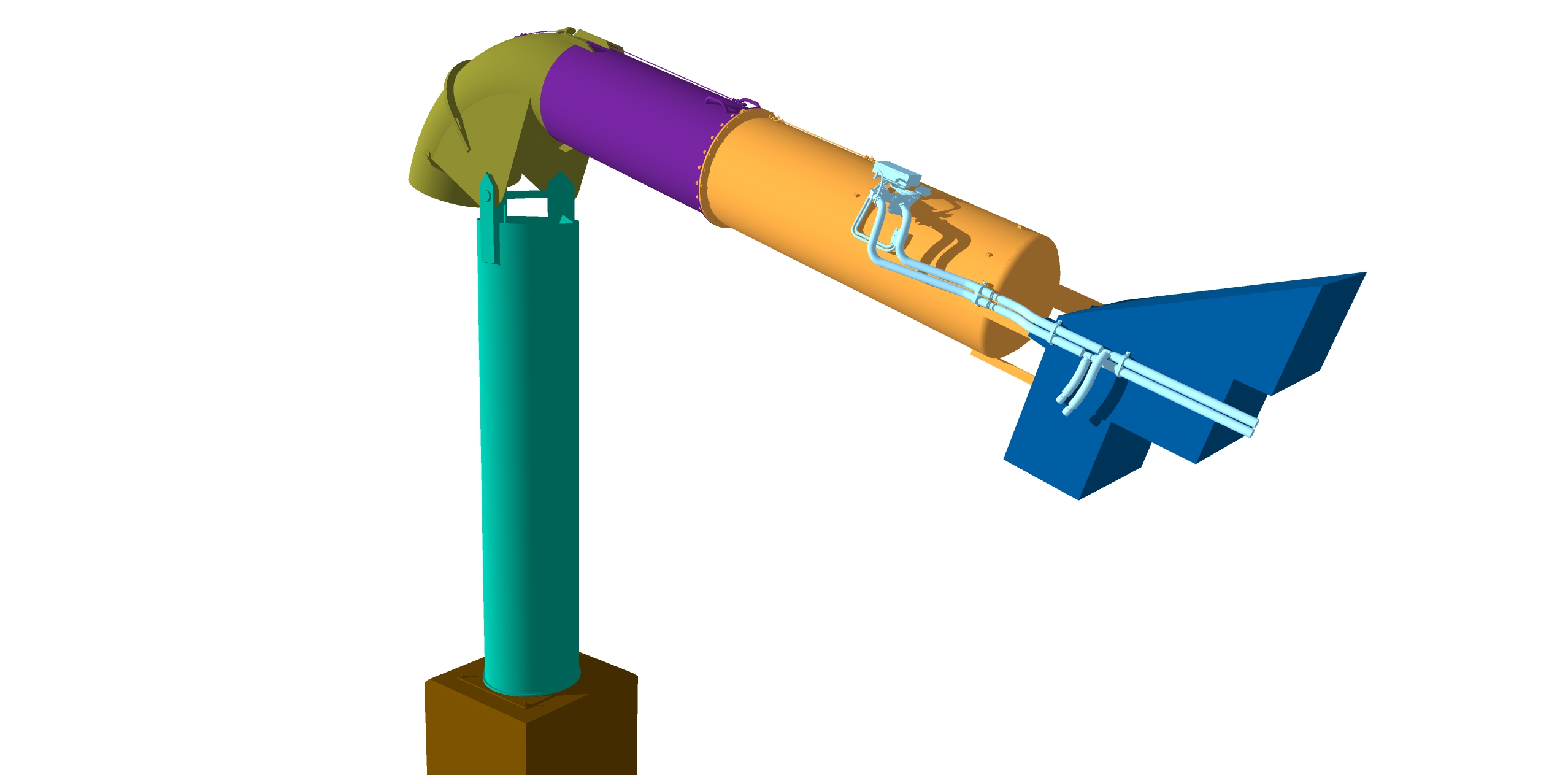
This is a standard 3m³ Gazex Exploder which is used to set off avalanche remotely in any weather condition. They work by filling a chamber with gas and detonating the propane and oxygen mixture. The exploders are connected to a central gas shelter capable of storing sufficient gas reserves for the entire season. The blast causes a huge shock-wave that triggers a avalanche. They are very expensive (about ¼ million dollars each) and are common on ski areas in Europe, not so very common elsewhere. In this model it show all the different components that make up exploder.


The standard 3m³ Gazex Exploder.


In this 3D model, I have modelled the avalanche start zone of one of the avalanche paths in my research area. A 1 metre digital terrain model generated from our LiDAR was used to create the terrain surface. Next, in the model I place three standard 3 m³ Gazex Exploders and one central gas shelter in there proposed positions. A Gazex system will be installed to protect both the infrastructure and a ski lift below this avalanche path. And finally to enhance the model I added some rocky outcrops and shadow effects.

Offline Rokket

  • Administrator
  • *
  • Posts: 2,362
  • Gender: Male
  • Submarine Enthusiast
    • AMP - Accurate Model Parts
Re: VIIC/41 - Schematices drawing
« Reply #1280 on: 29 Oct , 2014, 21:47 »
I know what this REALLY means...you're converting all your drawings to 3D so you can print one piece by piece...you can't fool me!
AMP - Accurate Model Parts - http://amp.rokket.biz

Offline NZSnowman

  • Admiral4
  • *
  • Posts: 2,419
  • Gender: Male
  • U-1308
    • U-1308 - Wikipedia
Re: VIIC/41 - Schematices drawing
« Reply #1281 on: 11 Nov , 2014, 01:37 »
I wonder what this could be the start of?  ;)


Offline SG

  • Admiral
  • *
  • Posts: 661
    • https://3xblackcats.wordpress.com/
Re: VIIC/41 - Schematices drawing
« Reply #1282 on: 10 May , 2015, 08:57 »
LM 43U Mount
The LM 43U mount was the final deign of mount used on U-boats. It further improvement on the LM 42U. The LM 43U was only known to be installed on three U-boats (U-1171, U-1305 and U-1306).


Simon, I found that U977 had a single 3.7cm/LM 43U-mounted gun too. Below, the conning tower of U-977 at La Plata


« Last Edit: 10 May , 2015, 09:07 by SG »

Offline NZSnowman

  • Admiral4
  • *
  • Posts: 2,419
  • Gender: Male
  • U-1308
    • U-1308 - Wikipedia
Re: VIIC/41 - Schematices drawing
« Reply #1283 on: 11 May , 2015, 13:15 »
Great found!

I have added this new information to my U-boat database.

Offline NZSnowman

  • Admiral4
  • *
  • Posts: 2,419
  • Gender: Male
  • U-1308
    • U-1308 - Wikipedia
Re: VIIC/41 - Schematices drawing
« Reply #1284 on: 31 May , 2015, 22:10 »
I had a bit of free time with my studies, so I modelled the FuMB-26 'Tunis' radar warning. The FuMB-26 combined 3 different radar warning systems, the ‘Naxos’, ‘Fliege’ & the ‘Mücke’. This system was used on U-boat from May/June 1944.

I have uploaded my 3D model of the FuMB-26 'Tunis' radar warning to my SketchUp '3D Warehouse' page. Anyone is welcome to download it. Below is a link to a free SketchUp viewer also.

Simon's 3D Warehouse' page
https://3dwarehouse.sketchup.com/model.html?id=u11d3de11-f1ef-4d76-8579-8eefe0ad4259

Free SketchUp Viewer
http://www.sketchup.com/products/sketchup-viewer


Offline NZSnowman

  • Admiral4
  • *
  • Posts: 2,419
  • Gender: Male
  • U-1308
    • U-1308 - Wikipedia
Re: VIIC/41 - Schematices drawing
« Reply #1285 on: 31 May , 2015, 22:21 »
Here the real thing :-)


Offline SG

  • Admiral
  • *
  • Posts: 661
    • https://3xblackcats.wordpress.com/
Re: VIIC/41 - Schematices drawing
« Reply #1286 on: 01 Jun , 2015, 11:30 »
Jaw-Dropping! Great, Great Work Simon!!

Offline NZSnowman

  • Admiral4
  • *
  • Posts: 2,419
  • Gender: Male
  • U-1308
    • U-1308 - Wikipedia
Re: VIIC/41 - Schematices drawing
« Reply #1287 on: 01 Jun , 2015, 12:54 »
Just a side note if you download the 3D model of the FuMB-26 'Tunis'. The model is drawn a 10x times larger to the real size of the FuMB-26 'Tunis'.

I do this because of how SketchUp draws small lines less of then 1 mm.

Offline NZSnowman

  • Admiral4
  • *
  • Posts: 2,419
  • Gender: Male
  • U-1308
    • U-1308 - Wikipedia
Re: VIIC/41 - Schematices drawing
« Reply #1288 on: 07 Jun , 2015, 02:17 »
Hi All

After 4 years of on and off research on the U-boat radar antenna I was finally able to determine how the German’s build the frame of the radar antenna. It may seem a small detail but I am very pleased to be able to work this out after some long  :)

I have uploaded my new 3D model of the FuMO 30 U-boat (radar) with FuMB 5 Samoa antennas (radar antenna warning) to my SketchUp '3D Warehouse' page.

Simon's 3D Model U-boats page
https://3dwarehouse.sketchup.com/collection.html?id=u4a2facb6-00be-441c-a5e5-ffd7a3c3549d


Offline NZSnowman

  • Admiral4
  • *
  • Posts: 2,419
  • Gender: Male
  • U-1308
    • U-1308 - Wikipedia
Re: VIIC/41 - Schematices drawing
« Reply #1289 on: 15 Jul , 2015, 19:07 »
FuMO-61 Hohentwiel U-boat Radar

The 3D model can be found here.
https://3dwarehouse.sketchup.com/model.html?id=u3f6389cc-b6f3-4415-a0d2-bedcba976755


Offline SG

  • Admiral
  • *
  • Posts: 661
    • https://3xblackcats.wordpress.com/
Re: VIIC/41 - Schematices drawing
« Reply #1290 on: 16 Jul , 2015, 11:44 »
Stunning, thanks for sharing!!

Offline Rokket

  • Administrator
  • *
  • Posts: 2,362
  • Gender: Male
  • Submarine Enthusiast
    • AMP - Accurate Model Parts
Re: VIIC/41 - Schematices drawing
« Reply #1291 on: 18 Jul , 2015, 21:36 »
ya, wow!
AMP - Accurate Model Parts - http://amp.rokket.biz

Offline NZSnowman

  • Admiral4
  • *
  • Posts: 2,419
  • Gender: Male
  • U-1308
    • U-1308 - Wikipedia
Re: VIIC/41 - Schematices drawing
« Reply #1292 on: 15 Aug , 2015, 00:40 »
I have uploaded a updated model to correct a number of very small error in the model.

FuMO-61 Hohentwiel U-boat Radar

The 3D model can be found here.
https://3dwarehouse.sketchup.com/model.html?id=u3f6389cc-b6f3-4415-a0d2-bedcba976755


Offline Rokket

  • Administrator
  • *
  • Posts: 2,362
  • Gender: Male
  • Submarine Enthusiast
    • AMP - Accurate Model Parts
Re: VIIC/41 - Schematices drawing
« Reply #1293 on: 22 Aug , 2015, 01:05 »
looks great, as always...a lot of nice detail work.
AMP - Accurate Model Parts - http://amp.rokket.biz

Offline falo

  • Admiral
  • *
  • Posts: 514
  • Gender: Male
Re: VIIC/41 - Schematices drawing
« Reply #1294 on: 02 Nov , 2015, 13:51 »
Hi Snowman,

there is interesting link from AMP Member "Old Noob" posted in the "Non Model Discussions" section:

http://models.rokket.biz/index.php?topic=1319.0

It's a photo report about the surrendered german boats after the end of WW2. Please take a look at the third pictures (caption: "German U-boats Surrender at Lisahally, Near Londonderry, Northern Ireland, 24 - 25 May 1945. U-boat crews unload ammunition and supplies from their craft").


I'am almost sure the picture is showing the alberich coated boat U-1105 (in the rear). If you zoom in, you can spot the rubber tiles grid on the conning tower The compass housing in front of the ct seems to be rubber coated too. The lower part of the Black Panther-emblem on top of the ct can be recognized as well.

Regards
falo
« Last Edit: 02 Nov , 2015, 13:55 by falo »

Offline NZSnowman

  • Admiral4
  • *
  • Posts: 2,419
  • Gender: Male
  • U-1308
    • U-1308 - Wikipedia
Re: VIIC/41 - Schematices drawing
« Reply #1295 on: 02 Nov , 2015, 14:35 »
Hi Snowman,

there is interesting link from AMP Member "Old Noob" posted in the "Non Model Discussions" section:

http://models.rokket.biz/index.php?topic=1319.0

It's a photo report about the surrendered german boats after the end of WW2. Please take a look at the third pictures (caption: "German U-boats Surrender at Lisahally, Near Londonderry, Northern Ireland, 24 - 25 May 1945. U-boat crews unload ammunition and supplies from their craft").


I'am almost sure the picture is showing the alberich coated boat U-1105 (in the rear). If you zoom in, you can spot the rubber tiles grid on the conning tower The compass housing in front of the ct seems to be rubber coated too. The lower part of the Black Panther-emblem on top of the ct can be recognized as well.

Regards
falo

Great spotting!

I have not noted that before... Yes, it U-1105.

U-1105 is the most photographic boat with alberic.

Offline Roel

  • Lieutenant (jg)
  • *
  • Posts: 61
Re: VIIC/41 - Schematices drawing
« Reply #1296 on: 12 Nov , 2015, 04:04 »
Simon,
Thank you for showing all these fantastic drawings! It is great to go through all this knowlege.
I wanted to improve upon the CMK interior for the engine room, since it became clear to me that it is rather lacking in accuracy.
I hope you have a drawing for the engine room and maybe the engine itself that I can look at?
Thank you for your time and effort!
Regards,
Roel

Offline OldNoob

  • Commander
  • *
  • Posts: 327
Re: VIIC/41 - Schematices drawing
« Reply #1297 on: 12 Nov , 2015, 06:01 »
Great info and illustration! There are some seriously knowledgeable and talented people in this forum.

Offline NZSnowman

  • Admiral4
  • *
  • Posts: 2,419
  • Gender: Male
  • U-1308
    • U-1308 - Wikipedia
Re: VIIC/41 - Schematices drawing
« Reply #1298 on: 17 Nov , 2015, 19:13 »
New drawing of the FuMO-61 Hohentwiel U-boat Radar


Old drawing of the FuMO-61 Hohentwiel U-boat Radar


Offline NZSnowman

  • Admiral4
  • *
  • Posts: 2,419
  • Gender: Male
  • U-1308
    • U-1308 - Wikipedia
Re: VIIC/41 - Schematices drawing
« Reply #1299 on: 30 Nov , 2015, 14:40 »
Schnorchel Restraining Bracket

When the Schnorchel mast is upright it is contained within the Schnorchel restraining bracket, which is located at the top of the conning tower. The schnorchel mast is locked into position by a large locking pin, which is controlled from within the Control Room.

Tore, grease line I estimate about 8 mm?

3-D model upload to https://3dwarehouse.sketchup.com/collection.html?id=u4a2facb6-00be-441c-a5e5-ffd7a3c3549d


« Last Edit: 30 Nov , 2015, 14:48 by NZSnowman »

Offline SG

  • Admiral
  • *
  • Posts: 661
    • https://3xblackcats.wordpress.com/
Re: VIIC/41 - Schematices drawing
« Reply #1300 on: 01 Dec , 2015, 11:52 »
Wow!!! :o

Offline NZSnowman

  • Admiral4
  • *
  • Posts: 2,419
  • Gender: Male
  • U-1308
    • U-1308 - Wikipedia
Re: VIIC/41 - Schematices drawing
« Reply #1301 on: 01 Dec , 2015, 17:30 »
FuMB Ant. 3 - Bali I antenna

This radar detections antenna FuMB 3 - Bali was used with the FuMB-1 Metox, FuMB-7 Naxos U, FuMB-8 Cypern I, FuMB-9 Cypern II and the FuMB-10 Borkum radar detections.

I will upload the 3-D model soon.


Offline NZSnowman

  • Admiral4
  • *
  • Posts: 2,419
  • Gender: Male
  • U-1308
    • U-1308 - Wikipedia
Re: VIIC/41 - Schematices drawing
« Reply #1302 on: 03 Dec , 2015, 00:28 »
For all my drawings I always try to use as many of the original German measurements I can. I haven’t got a full set of original German measurements for the Schnorchel. So I used what I can find from both the Type VII and Type IX measurements and presuming that the Germans use both the same Schnorchel mast for each boat.

I just realise that the Schnorchel masts measurements are not the same for both the Type VII and Type IX this means that all my Schnorchel drawings are incorrect. So caution is needed if using my Schnorchel drawings.

I will correct this, but it will take me a few good days to do this.
 
You may notice this is the second time (http://models.rokket.biz/index.php?topic=1166.msg18402#msg18402) that one of my drawings measurements are incorrect in the last few weeks. The reason why I picking up these errors now is because I am modelling parts of the U-boat in 3D. Modelling the U-boat in 3-D takes a lots more time to do but I’m picking up errors in my measurements quite easily.

Schnorchel Restraining Bracket

When the Schnorchel mast is upright it is contained within the Schnorchel restraining bracket, which is located at the top of the conning tower. The schnorchel mast is locked into position by a large locking pin, which is controlled from within the Control Room.

Tore, grease line I estimate about 8 mm?

3-D model upload to https://3dwarehouse.sketchup.com/collection.html?id=u4a2facb6-00be-441c-a5e5-ffd7a3c3549d


« Last Edit: 03 Dec , 2015, 02:20 by NZSnowman »

Offline David83

  • Lieutenant (jg)
  • *
  • Posts: 70
  • Gender: Male
Re: VIIC/41 - Schematices drawing
« Reply #1303 on: 03 Dec , 2015, 01:54 »

Anyway you are doing a fantastic outstandig work of Research and drawings.

wbr David

Offline NZSnowman

  • Admiral4
  • *
  • Posts: 2,419
  • Gender: Male
  • U-1308
    • U-1308 - Wikipedia
Re: VIIC/41 - Schematices drawing
« Reply #1304 on: 04 Dec , 2015, 13:55 »
New and corrected Schnorchel drawings.


Offline NZSnowman

  • Admiral4
  • *
  • Posts: 2,419
  • Gender: Male
  • U-1308
    • U-1308 - Wikipedia
Re: VIIC/41 - Schematices drawing
« Reply #1305 on: 04 Dec , 2015, 14:10 »
May have got carry away with is model… I model the Tarnmatte in 3-D  ;D ;D


Offline falo

  • Admiral
  • *
  • Posts: 514
  • Gender: Male
Re: VIIC/41 - Schematices drawing
« Reply #1306 on: 05 Dec , 2015, 00:56 »
Hi Snowman,


once more: thank you very much for sharing.


Regards
Falo

Offline NZSnowman

  • Admiral4
  • *
  • Posts: 2,419
  • Gender: Male
  • U-1308
    • U-1308 - Wikipedia
Re: VIIC/41 - Schematices drawing
« Reply #1307 on: 10 Dec , 2015, 12:47 »
I have uploaded the new 3-D model of the Schnorchel restraining bracket.

https://3dwarehouse.sketchup.com/collection.html?id=u4a2facb6-00be-441c-a5e5-ffd7a3c3549d

Schnorchel Restraining Bracket

When the Schnorchel mast is upright it is contained within the Schnorchel restraining bracket, which is located at the top of the conning tower. The schnorchel mast is locked into position by a large locking pin, which is controlled from within the Control Room.

Tore, grease line I estimate about 8 mm?

3-D model upload to https://3dwarehouse.sketchup.com/collection.html?id=u4a2facb6-00be-441c-a5e5-ffd7a3c3549d


Offline tore

  • Tore
  • *
  • Posts: 2,539
  • Gender: Male
Re: VIIC/41 - Schematices drawing
« Reply #1308 on: 10 Dec , 2015, 14:45 »
Simon I guess the  8mm greaseline for the threaded locking pin should be OK, may be a fraction larger see the photo below of the locking pin for U- 968.
As you probably know there is a second lockingpin securing the mast when lowered in the casing. The mast has a simple lid engaging the securingclamp by turning a handle up at the pressurehull in the COs cabin as you can see on my sktech below. In addition you have the mast position indicator up in the pressurehull in the Control room next to the hydraulic handle for the lowering and raising of the mast see the image below.
Tore

Offline OldNoob

  • Commander
  • *
  • Posts: 327
Re: VIIC/41 - Schematices drawing
« Reply #1309 on: 10 Dec , 2015, 15:40 »
Was this part of the Schnorchel cast aluminum or wire on steel? The ribbing gives me that impression.
« Last Edit: 10 Dec , 2015, 19:07 by OldNoob »

Offline NZSnowman

  • Admiral4
  • *
  • Posts: 2,419
  • Gender: Male
  • U-1308
    • U-1308 - Wikipedia
Re: VIIC/41 - Schematices drawing
« Reply #1310 on: 10 Dec , 2015, 19:53 »
Late war UZO (Underwasserzieloptik) with Carl Zeiss U-boat 7x50 binoculars (painted grey, with folding sight to top, additional tube extensions with covers to front, fold-up eye pieces).


Offline tore

  • Tore
  • *
  • Posts: 2,539
  • Gender: Male
Re: VIIC/41 - Schematices drawing
« Reply #1311 on: 10 Dec , 2015, 23:36 »
Was this part of the Schnorchel cast aluminum or wire on steel? The ribbing gives me that impression.
The homingbracket for the schnorchelmast was welded steel, the reason for the strengtening ribs is that you get a tremendous load on the mast both alongship as well as atwart and you don`t want to transfer those stresses to the fulcrum being susceptible to sidestresses which might create leakages and even breakages.
May be this is an answer of a different question as yours might refer to the Tarnmatte?
Tore
« Last Edit: 10 Dec , 2015, 23:42 by tore »

Offline NZSnowman

  • Admiral4
  • *
  • Posts: 2,419
  • Gender: Male
  • U-1308
    • U-1308 - Wikipedia
Re: VIIC/41 - Schematices drawing
« Reply #1312 on: 13 Dec , 2015, 11:29 »
Hi Maciek

Did they used the same UZO (Underwasserzieloptik) on both the Type VIIC's and Type IX (namely the late war UZO) ?

Thank's Simon

Offline NZSnowman

  • Admiral4
  • *
  • Posts: 2,419
  • Gender: Male
  • U-1308
    • U-1308 - Wikipedia
Re: VIIC/41 - Schematices drawing
« Reply #1313 on: 13 Dec , 2015, 16:49 »
Does anyone if the sky and attack periscope has the same maximum diameter (180 mm)?

Offline NZSnowman

  • Admiral4
  • *
  • Posts: 2,419
  • Gender: Male
  • U-1308
    • U-1308 - Wikipedia
Re: VIIC/41 - Schematices drawing
« Reply #1314 on: 13 Dec , 2015, 17:15 »
Does anyone if the sky and attack periscope has the same maximum diameter (180 mm)?

Find the anwer - Yes :)

Offline NZSnowman

  • Admiral4
  • *
  • Posts: 2,419
  • Gender: Male
  • U-1308
    • U-1308 - Wikipedia
Re: VIIC/41 - Schematices drawing
« Reply #1315 on: 14 Dec , 2015, 00:05 »
Just upload a new 3-D model of the Nacht-Luftziel-Sehrohr Carl Zeiss Periscope NLSR C/7.

https://3dwarehouse.sketchup.com/model.html?id=ue3e1fe02-643c-47d1-b169-02190b029b72

Offline NZSnowman

  • Admiral4
  • *
  • Posts: 2,419
  • Gender: Male
  • U-1308
    • U-1308 - Wikipedia
Re: VIIC/41 - Schematices drawing
« Reply #1316 on: 17 Dec , 2015, 00:29 »
Dougie, were the late war Type VIIC/41 painted all in dunkelgrau 52 (dark grey - RAL 7024)?

The  Type VIIC/41 seen darker than the early boats.

Offline dougie47

  • Administrator
  • *
  • Posts: 758
Re: VIIC/41 - Schematices drawing
« Reply #1317 on: 17 Dec , 2015, 14:42 »
Hello Simon,

It is not possible to provide a definitive answer to this question. Yes, you are correct in thinking that late war boats were in general darker than early boats. There were very few light grey boats by the end of the war. Most were either quite dark or dark grey.

The lower hull was RAL7016, as we know.

I have looked again at the painting regulations for 1944 and they state (for upper hull and tower) that 58 was to be used. There were three types of 58 paint but it doesn't state which version of 58. There were three versions (58 Schlickgrau; 58/1 Blaugrau; 58/2 Blauschwarz). It isn't possible to tell from a b&w photo whether a boat had Schlickgrau or Blaugrau. Blauschwarz is very dark indeed but probably was used on some boats (U 1052 for example).

Although the regulations state 58, there may have been cases (with paint stocks being low and supply issues) where Dunkelgrau 52 could have been used on some boats. Certainly some boats were as dark as Dunkelgrau 52.

If you are debating what colour to choose for your drawing it might be best to play it safe and go for one of the 58 colours as that is what is in the regulations. What boat are you drawing and at what time?

You probably already realise this but the present paint colour of U 995 is not representative of a typical late war boat.

Cheers,

Dougie


Offline NZSnowman

  • Admiral4
  • *
  • Posts: 2,419
  • Gender: Male
  • U-1308
    • U-1308 - Wikipedia
Re: VIIC/41 - Schematices drawing
« Reply #1318 on: 18 Dec , 2015, 01:22 »
I am thinking U-1305

I wonder the reason they were are darker was by the war they were on the surface only at night time.

I will try Blaugrau 58/1 on the tower first.

Offline NZSnowman

  • Admiral4
  • *
  • Posts: 2,419
  • Gender: Male
  • U-1308
    • U-1308 - Wikipedia
Re: VIIC/41 - Schematices drawing
« Reply #1319 on: 18 Dec , 2015, 02:26 »
Schlickgrau 58-1 LifeColor UA 609


Dunkelgrau 52 - LifeColor UA 610


Dunkelgrau 52 - RAL 7024 (CMYK)


Offline dougie47

  • Administrator
  • *
  • Posts: 758
Re: VIIC/41 - Schematices drawing
« Reply #1320 on: 18 Dec , 2015, 06:43 »
Hi Simon,
 
I'm looking at the Lifecolor UA608 Schlickgrau and UA 609 Blaugrau colours and comparing them to the Snyder & Short paint cards. The Blaugrau is not too bad. But the Schlickgrau does not look the same at all (it doesn't have the mud-gray look  at all). There are quite major differences between colours on computer screens (the colours look different between my PC and laptop) so this makes this exercise particularly difficult.
 
When I was researching paint colours I obtained a diskette from RAL and these give the following RGB and CMYK codes -
 
RAL7000 RGB - 120/131/137    CMYK - 40/10/10/40 (Dunkelgrau 51)
RAL7001 RGB - 137/145/150    CMYK - 10/0/0/40 (supposedly Hellgrau 50 but I have doubts)
RAL7016 RGB - 54/61/65   CMYK - 60/30/30/80 (Dunkelgrau 53 + lower hull colour)
RAL7024 RGB - 62/65/70    CMYK - 80/60/50/40 (Dunkelgrau 52)
 
Unfortunately there are no RAL codes for the 58 colours. I tried to approximate the 58 colours to find RGB values and these are the codes I came up with -
 
Schlickgrau 58 - RGB - 77 / 81 / 76
Blaugrau 58/1 - RGB - 73 / 78 / 78
Blauschwarz 58/2 - RGB - 22 / 34 / 34
 
These codes looked like the S&S paint cards on the monitor I was using at the time. Just to further complicate matters, some computer screens look darker than others and on my current monitor they look a bit too dark (groan). I would recommend trying the RGB values above for Schlickgrau and Blaugrau and see how they look.
 
Cheers,
 
Dougie


Offline NZSnowman

  • Admiral4
  • *
  • Posts: 2,419
  • Gender: Male
  • U-1308
    • U-1308 - Wikipedia
Re: VIIC/41 - Schematices drawing
« Reply #1321 on: 18 Dec , 2015, 12:10 »
Dougie, the new colours look great :D

I like both Blaugrau 58/1 & Blauschwarz 58/2

Schlickgrau 58 - RGB - 77 / 81 / 76


Blaugrau 58/1 - RGB - 73 / 78 / 78


Blauschwarz 58/2 - RGB - 22 / 34 / 34

Offline dougie47

  • Administrator
  • *
  • Posts: 758
Re: VIIC/41 - Schematices drawing
« Reply #1322 on: 19 Dec , 2015, 05:05 »
Hi Simon,
 
Looking very good. Going by the U 1305 commissioning photo you will need a colour lighter for the upper hull and tower than the lower hull. I'd say Blauschwarz 58/2 would be too dark. But Blaugrau 58/1 - that would work just nicely.
 
Have you added RAL7016 to the lower hull?
 
I see you have kept kept the UZO top and binoculars light grey. Good spot - they did tend to keep these items in light grey.
 
Cheers,
 
Dougie

Offline NZSnowman

  • Admiral4
  • *
  • Posts: 2,419
  • Gender: Male
  • U-1308
    • U-1308 - Wikipedia
Re: VIIC/41 - Schematices drawing
« Reply #1323 on: 30 Dec , 2015, 01:49 »
Does anyone know what these are? ???

I found them on the lower wintergaten, and I believe also on the upper wintergaten. I have never noted them before :-[


Offline NZSnowman

  • Admiral4
  • *
  • Posts: 2,419
  • Gender: Male
  • U-1308
    • U-1308 - Wikipedia
Re: VIIC/41 - Schematices drawing
« Reply #1324 on: 30 Dec , 2015, 22:51 »
Tore, what could these two valves (you can see a 'T' handle in one of the hole) be for?


Offline OldNoob

  • Commander
  • *
  • Posts: 327
Re: VIIC/41 - Schematices drawing
« Reply #1325 on: 31 Dec , 2015, 00:48 »
I have wondered this as well NZ. Im guessing the T-bar would indicate access to a valve of some sort. Great find on the photo!
« Last Edit: 31 Dec , 2015, 00:51 by OldNoob »

Offline NZSnowman

  • Admiral4
  • *
  • Posts: 2,419
  • Gender: Male
  • U-1308
    • U-1308 - Wikipedia
Re: VIIC/41 - Schematices drawing
« Reply #1326 on: 31 Dec , 2015, 00:53 »
I have wondered this as well NZ Im guessing the T-bar would indicate access to a valve of some sort.

Yes, I believe a valve but nothing show up on my under the decking piping drawing :(

Offline OldNoob

  • Commander
  • *
  • Posts: 327
Re: VIIC/41 - Schematices drawing
« Reply #1327 on: 31 Dec , 2015, 03:10 »
Ya know.... just looking at it. .. this may be a silly thought but, could it be that the holes are simply there to temporarily hold the pry bar or t-bar used to open or work in some of those access doors? and to keep that bar from sliding or being kicked off the deck?

Offline NZSnowman

  • Admiral4
  • *
  • Posts: 2,419
  • Gender: Male
  • U-1308
    • U-1308 - Wikipedia
Re: VIIC/41 - Schematices drawing
« Reply #1328 on: 31 Dec , 2015, 18:15 »
Does anyone know what these are? ???

I found them on the lower wintergaten, and I believe also on the upper wintergaten. I have never noted them before :-[


I think I workout that the two cut out on the deck are for. I believe they are locking handle for the large wooden hatch next to it. They used the same locking handle style on the Galley Hatch.
« Last Edit: 31 Dec , 2015, 23:55 by NZSnowman »

Offline NZSnowman

  • Admiral4
  • *
  • Posts: 2,419
  • Gender: Male
  • U-1308
    • U-1308 - Wikipedia
Re: VIIC/41 - Schematices drawing
« Reply #1329 on: 01 Jan , 2016, 00:48 »
Does anyone know what these are? ???

I found them on the lower wintergaten, and I believe also on the upper wintergaten. I have never noted them before :-[


Below this the Ammunition Container on the late war Type VIIC's. The Ammunition Container is different on the earlier Type VIIC's and the Type IX's.

« Last Edit: 01 Jan , 2016, 00:58 by NZSnowman »

Offline Capt Kremin

  • Commander
  • *
  • Posts: 273
  • Gender: Male
Re: VIIC/41 - Schematices drawing
« Reply #1330 on: 01 Jan , 2016, 01:16 »
Hi Simon,'


Makes sense. The Gallery hatch is part of the original build and so would have common fittings, whereas the various turms seem to be local brews based on a general set of plans so the hatch in view could have been retained with an adhoc mechanism, if not unique it could have been used either by one shipyard or even one construction crew.
This custom building is more noticeable with the type IXs where each boat seems to have a unique detail on it, perhaps this is so due to there being less of then, but I believe that the same diversity of fit and finish exists on the type VIIs, it's just with the numbers built it is harder to spot. I suspect that the Captains had a certain amount of say in how the turm was fitted out during upgrades, along with material availability gives each boat a good change of being unique,


Speaking of such things your latest post with the ammo container reminds me of of the diversity of the number and locations of the ready containers, (ammo and life raft).


Regards
Jon
"Here's Peter Jason Quill, He's also called Starlord",
"Who calls him that?",
"Himself Mostly".

Offline OldNoob

  • Commander
  • *
  • Posts: 327
Re: VIIC/41 - Schematices drawing
« Reply #1331 on: 01 Jan , 2016, 02:47 »
I think I workout that the two cut out on the deck are for. I believe they are locking handle for the large wooden hatch next to it. They used the same locking handle style on the Galley Hatch.

Nice!

Offline NZSnowman

  • Admiral4
  • *
  • Posts: 2,419
  • Gender: Male
  • U-1308
    • U-1308 - Wikipedia
Re: VIIC/41 - Schematices drawing
« Reply #1332 on: 01 Jan , 2016, 11:54 »
Just upload the Ammunition Container to my 3DWarehouse page.

https://3dwarehouse.sketchup.com/collection.html?id=u4a2facb6-00be-441c-a5e5-ffd7a3c3549d

Offline NZSnowman

  • Admiral4
  • *
  • Posts: 2,419
  • Gender: Male
  • U-1308
    • U-1308 - Wikipedia
Re: VIIC/41 - Schematices drawing
« Reply #1333 on: 01 Jan , 2016, 14:46 »
While researching the top hand rail around the upper Wintergarten I noted that the Germans charge the style near to the end of the war.

Reason why? Perhaps to save metal (3.5% less steel) and/or construction time?  ???

Style 1 - Early to mid War, follow the contour of the deck below.
Style 2 - Late War - More arounded.


Fig. 1. Style 2 (left) and style 1 (right)


Fig. 2. Style 1 Yellow and style 2 pink.

Offline OldNoob

  • Commander
  • *
  • Posts: 327
Re: VIIC/41 - Schematices drawing
« Reply #1334 on: 01 Jan , 2016, 14:58 »
Could it also been a matter of different Ships yards doing things slightly different?

From the picture, it also looks like where the stanchions attach to the upper wintergarden is also a bit different.
In fact the actual shape of the wintergarden decks also look different. One is more rounded and one seems to be more rectangular
« Last Edit: 01 Jan , 2016, 15:02 by OldNoob »

Offline Capn Tucker

  • Ensign
  • *
  • Posts: 41
  • Gender: Male
Re: VIIC/41 - Schematices drawing
« Reply #1335 on: 01 Jan , 2016, 18:16 »
I would tend to go with the different shipyards theory. The requirement was probably just that there needed to be a railing there, and not that they all had to be done in exactly the same way. Then there could be repairs to battle damage etc. Could have been a replacement installed at the pier or in drydock, and with whatever was handy.
Same thing with limber holes. They varied from yard to yard, from boat to boat, different time periods etc etc..

Offline SG

  • Admiral
  • *
  • Posts: 661
    • https://3xblackcats.wordpress.com/
Re: VIIC/41 - Schematices drawing
« Reply #1336 on: 02 Jan , 2016, 10:22 »
Well done Simon, for spotting the details!

Offline NZSnowman

  • Admiral4
  • *
  • Posts: 2,419
  • Gender: Male
  • U-1308
    • U-1308 - Wikipedia
Re: VIIC/41 - Schematices drawing
« Reply #1337 on: 02 Jan , 2016, 21:27 »
I would tend to go with the different shipyards theory. The requirement was probably just that there needed to be a railing there, and not that they all had to be done in exactly the same way. Then there could be repairs to battle damage etc. Could have been a replacement installed at the pier or in drydock, and with whatever was handy.
Same thing with limber holes. They varied from yard to yard, from boat to boat, different time periods etc etc..

Could it also been a matter of different Ships yards doing things slightly different?

From the picture, it also looks like where the stanchions attach to the upper wintergarden is also a bit different.
In fact the actual shape of the wintergarden decks also look different. One is more rounded and one seems to be more rectangular

I can tell you one thing, and that is Style 2 the late war arounded railing as not design with a CAD progam or draftsman!

Nothing this symmetrical or mathematically curved! It’s been a nightmare trying to get them to work together. I ended up free handing most of the railing to make it look natural and to look like the wartime photos.

I’d almost say for almost certain that these rails were designed and constructed by the shipyard workers completely.
 

Offline NZSnowman

  • Admiral4
  • *
  • Posts: 2,419
  • Gender: Male
  • U-1308
    • U-1308 - Wikipedia
Re: VIIC/41 - Schematices drawing
« Reply #1338 on: 03 Jan , 2016, 03:36 »
Style 2 the late war rounded railing


Offline OldNoob

  • Commander
  • *
  • Posts: 327
Re: VIIC/41 - Schematices drawing
« Reply #1339 on: 03 Jan , 2016, 06:12 »
LOVE it!

I was thinking maybe since that upper railing is not round but rather somewhat oval or flattened, maybe it was just easier for the ship builders to make sweeping cures as opposed to hard angles.
« Last Edit: 03 Jan , 2016, 06:14 by OldNoob »

Offline falo

  • Admiral
  • *
  • Posts: 514
  • Gender: Male
Re: VIIC/41 - Schematices drawing
« Reply #1340 on: 03 Jan , 2016, 11:31 »
Hi Gents,


Thanks for the new ct drawings. I suppose the pipes under the upper platform are containers for spare barrels for the 3,7 cm AA gun.


Just a question: Do you have frame drawings for the ct? Maybe from some original source?


Best regards and thanks in advance
Falo

Offline NZSnowman

  • Admiral4
  • *
  • Posts: 2,419
  • Gender: Male
  • U-1308
    • U-1308 - Wikipedia
Re: VIIC/41 - Schematices drawing
« Reply #1341 on: 03 Jan , 2016, 11:43 »
LOVE it!

I was thinking maybe since that upper railing is not round but rather somewhat oval or flattened, maybe it was just easier for the ship builders to make sweeping cures as opposed to hard angles.

My curve is not 100% correct (about +90% correct) I just could not match all the curve to match the war time photos. With better photo, especially from above, I may get it 100% correct.
 
You have a very good point about “easier for the ship builders to make sweeping cures as opposed to hard angles”. I can imagine the dockworker taking a pipe bender up on the deck and slowly bending the pipe and testing to see if it fit, and repeating the process until it does.

Offline NZSnowman

  • Admiral4
  • *
  • Posts: 2,419
  • Gender: Male
  • U-1308
    • U-1308 - Wikipedia
Re: VIIC/41 - Schematices drawing
« Reply #1342 on: 03 Jan , 2016, 12:12 »

Thanks for the new ct drawings. I suppose the pipes under the upper platform are containers for spare barrels for the 3,7 cm AA gun.


Yes, the pipes are the spare barrels for the 3.7 cm Flak guns.
 
If you are going to add the spare barrels be aware that there are two styles.

Style 1. War late - Usual position.
Style 2. U-boats constructed by Flensburger Schiffbau-Gesellschaft, Flensburg, they lower the angle of the spare barrels to about 3 degs, nearly flat. Like my drawing. Reason unknown?


Just a question: Do you have frame drawings for the ct? Maybe from some original source?


I have never seen any frame diagrams, drawings or original German measurements of the turms. I have seen a very few of the conning tower original measurements, but they are a little conflicting with other measurements of seen. I need to do some more research in this area and see which ones are correct.

There are a few line drawing of late war Type VIIC’s and Type VIIC/41’s but I would not expect them to be accurate, they are okay only for a guide.
« Last Edit: 03 Jan , 2016, 12:14 by NZSnowman »

Offline NZSnowman

  • Admiral4
  • *
  • Posts: 2,419
  • Gender: Male
  • U-1308
    • U-1308 - Wikipedia
Re: VIIC/41 - Schematices drawing
« Reply #1343 on: 03 Jan , 2016, 21:49 »
Hi NZSnowman,


To clarify
M42 LM42U single 3.7cm fitted to both type VIIs and type IXs
C38 DLM43U twin 2cm fitted both types. DLM43U would not have been able to support the 3.7cm M42 or M43
M43 LM42U single 3.7cm fitted to type VIIs and type IXs, cheaper to manufacture, greater rate of fire, shorter range (and barrel)
M42 DLM42U twin 3.7cm - U boats ]
M43 DLM42U twin 3.7cm - U boats ]same mount, just different gun[size=78%]


Or the short answer the M43 I was previously referring to was the gun not the mount. The M43 was definitely fitted to at least one U Boat, the U 534, so was most probably fitted to other boats that had their single 3.7cm upgraded to a twin during the latter months of the war, no exact date for the U 534s fitment but sometime after October '44. It would not have been necessary to develop a new mount for the M43 as its pivot point and firing linkage are virtually identical to the M42. To be honest it is very difficult to spot the difference between the M42 and M43 in wartime photos.


Regards
Jon

Jon, I was wondering if you have seen any original German dimensions for the 2cm Flak C/38 II M 43 U?

I estimate the base at 580 mm wide.

Offline Capt Kremin

  • Commander
  • *
  • Posts: 273
  • Gender: Male
Re: VIIC/41 - Schematices drawing
« Reply #1344 on: 03 Jan , 2016, 22:29 »
Hi Simon,


I will check next weekend, I am currently away from home.


Regards
Jon
"Here's Peter Jason Quill, He's also called Starlord",
"Who calls him that?",
"Himself Mostly".

Offline falo

  • Admiral
  • *
  • Posts: 514
  • Gender: Male
Re: VIIC/41 - Schematices drawing
« Reply #1345 on: 04 Jan , 2016, 15:37 »
Hi Snowman,

thanks for your answers.

I think I know what you mean: The famous VIIC outlines from Koehl are partly redrawings made in 1975 and 1985. The stern drawing is dated from 1988. But – as we all suppose here – every single yard had is own individual building style. So IMO Koehls drawings are a good base to derive a particular VIIC U boat. But as you said for that endeavor a lot of good pictures and imagination are required. 

Regards
falo

Offline NZSnowman

  • Admiral4
  • *
  • Posts: 2,419
  • Gender: Male
  • U-1308
    • U-1308 - Wikipedia
Re: VIIC/41 - Schematices drawing
« Reply #1346 on: 04 Jan , 2016, 19:07 »
Hi Simon,


I will check next weekend, I am currently away from home.


Regards
Jon

Thanks

Offline NZSnowman

  • Admiral4
  • *
  • Posts: 2,419
  • Gender: Male
  • U-1308
    • U-1308 - Wikipedia
Re: VIIC/41 - Schematices drawing
« Reply #1347 on: 05 Jan , 2016, 00:39 »
Today I found a little detail that has been missing.
 
Most (maybe all) drawings/ plans and the Revell 1:72 Scale Type VIIC/41 have four ladder rungs up to the upper platform. But if you look carefully at war time photo’s you will see that the Germans use the hand rail for the second ladder rung. The hand rail was a little close to the casing so they dogleg the rail out a little to match the other ladder rung.


Offline NZSnowman

  • Admiral4
  • *
  • Posts: 2,419
  • Gender: Male
  • U-1308
    • U-1308 - Wikipedia
Re: VIIC/41 - Schematices drawing
« Reply #1348 on: 06 Jan , 2016, 22:30 »
Schnorchel restraining bracket with locking pin and control arm.

Grease lines can be seen going under the tower casting

« Last Edit: 06 Jan , 2016, 22:33 by NZSnowman »

Offline OldNoob

  • Commander
  • *
  • Posts: 327
Re: VIIC/41 - Schematices drawing
« Reply #1349 on: 07 Jan , 2016, 09:51 »
Awesome work. Keep it up! Looking forward to viewing the complete model in some form of interactive method.

Offline NZSnowman

  • Admiral4
  • *
  • Posts: 2,419
  • Gender: Male
  • U-1308
    • U-1308 - Wikipedia
Re: VIIC/41 - Schematices drawing
« Reply #1350 on: 07 Jan , 2016, 15:04 »
Dougie,

I was wondering about your thoughts on the lower wintergaten railing.

I have noted that most of the late war Type VIIC & VIIC/41 have a ring a netting around the lower part of the lower wintergaten. What the purpose of this netting is it to stop the empty cartridges of the 3.7 cm Flak going overboard?

I have also noted that on the very late war Type VIIC/41 this netting is a completely missing. To me it seems like the Germans just didn’t bother anymore about the netting this late in the war, perhaps for the reason they were using the Flak guns so little.

Any thoughts about this netting on the lower wintergaten?

Offline dougie47

  • Administrator
  • *
  • Posts: 758
Re: VIIC/41 - Schematices drawing
« Reply #1351 on: 09 Jan , 2016, 14:03 »
Hi Simon,
 
I have had no success researching this subject. Partly this is because the netting is difficult to observe from a distance. From a certain distance it is difficult to establish for certainty whether it was there or not.
 
Unfortunately I have yet to establish any sort of pattern. I've not seen it on many VIICs/VIIC/41s at all. I suspect many VIICs did not get this at all. It is there on a few boats in spring 1944 (but not on others). Whether a boat would retain the feature until the end of the war I don't know. The other difficulty is that the netting wasn't always in the same place. On either U 953 or U 275 it was to half height on the upper platform but I don't know if it was on the lower platform.
 
It seems to me to be more common on IXs but there were plenty of IXs without the netting at all. Again the style differed. U 805 and U 516 at the end of the war both had the netting to quarter height (a quarter of the way up to the top railing bar) but only on the lower platform - not the upper platform.  U 190 at the war's end also had it on the lower platform only but on this boat it was to half height.
 
So I can't give you anything like a definitive answer. But we might venture to say that there does not appear to be one specific style of netting applied universally to all boats within a certain time frame.
 
As for the purpose, stopping empty cartridges going overboard, or even dropped full ones, seems quite a sensible guess.
 
Cheers,
 
Dougie
 

Offline NZSnowman

  • Admiral4
  • *
  • Posts: 2,419
  • Gender: Male
  • U-1308
    • U-1308 - Wikipedia
Re: VIIC/41 - Schematices drawing
« Reply #1352 on: 09 Jan , 2016, 16:58 »

Partly this is because the netting is difficult to observe from a distance. From a certain distance it is difficult to establish for certainty whether it was there or not.


Hi Dougie

Thanks for taking your time to answer.

You are totally correct about trying to pick out the netting in war time photo, it nearly impossible. It is critical to get just the right lighting so you can see the netting in the photographs.
 
Another thing I just been looking into recently is the late war UZO, there seen to be two sub-styles. The handle and basic layout are the same but the top and base of the late war UZO are different. One of the sub-style seems more common than the other. I will post some pictures in a few days after I finish drawing them. Have you noted this differences in late war UZO?

Offline falo

  • Admiral
  • *
  • Posts: 514
  • Gender: Male
Re: VIIC/41 - Schematices drawing
« Reply #1353 on: 10 Jan , 2016, 02:56 »
Hi Snowman, hi Dougie,

just checked my pictures from U 995 last night. Please look at the attached photo.

If the netting (upper and lower platform) on U 995 is accurate we can see a small space between the lower edge of the netting and the floor. IMO this space is small enough to stop cartridge magazines from going overboard during operating the AA-guns, but wide enough to let the empty shells drop into the water. Because empty shells would have been a triping hazard for the AA-gun crew.

Regards
falo
« Last Edit: 10 Jan , 2016, 03:03 by falo »

Offline SG

  • Admiral
  • *
  • Posts: 661
    • https://3xblackcats.wordpress.com/
Re: VIIC/41 - Schematices drawing
« Reply #1354 on: 10 Jan , 2016, 06:24 »
 
 
But we might venture to say that there does not appear to be one specific style of netting applied universally to all boats within a certain time frame.
 

I agree, I've been checking quite a number of pictures on U-Boot im focus and the styles of netting vary from boat to boat in terms of location (upper/lower wintergarten/both) and presence/absence of spacing  from lower edge of netting and floor.
A few examples:

- U 953 and U 415, April 1944; U 260 Oct 1943: netting on upper and lower wintergarten, no spacing. (U-boot im focus n.7 pages 51-52; UiF n.11 page 7, picture5; UiF n.5 page 8 Photo 7, respectively)
- U 249, U 1023, May 1945 (after ceasefire): netting on lower wintergarten on both boats, no spacing for U 1023, netting mounted on frame spaced from the edge of lower wintergarten on U 249. (U-boot im focus n.12 page 27, photo 21)
- Unknown boat, turm IV w Flak Vierling: net on upper and lower wintergarten reinforced at the base of netting with perforated metal sheet, no spacing at all (U-boot im focus n.2 page 6, photo 7)
- U 264, October 1943: perforated metal sheet instead of netting on upper and lower wintergarten (U-boot im focus n.11 page 11, photo 10)
Cheers,
SG   
« Last Edit: 10 Jan , 2016, 07:34 by SG »

Offline NZSnowman

  • Admiral4
  • *
  • Posts: 2,419
  • Gender: Male
  • U-1308
    • U-1308 - Wikipedia
Re: VIIC/41 - Schematices drawing
« Reply #1355 on: 10 Jan , 2016, 12:37 »
SG,

I noted on a few boat there a very smal tab (about 30 mm wide) between the lowest rail and rim of the floor and 1/2 between the rail posts.

Do you have any better photo's of them? Are they just supporting the lower rail? Are they just welded onto the rim of deck?

Offline Capt Kremin

  • Commander
  • *
  • Posts: 273
  • Gender: Male
Re: VIIC/41 - Schematices drawing
« Reply #1356 on: 10 Jan , 2016, 13:17 »
Hi Simon,


Sorry I have no measurement written down, only a couple of drawings. However all is not lost, which given measurements I have already taken of the U 534 I am less inclined to trust, I feel the need to make one more visit to the U 534, given her state of disrepair on my last visit it will not be a happy trip but I need to take a few more measurements and I have a better way of photographing the 3.7cm than previous.
They is a C38 in the indoor museum area which I can measure the base, it is a single mount but I am pretty sure that the bases were the same dimensions. Not sure when that will be, maybe Easter. If there is anything else that I maybe able to measure/photograph feel free to ask.


Regards
Jon
"Here's Peter Jason Quill, He's also called Starlord",
"Who calls him that?",
"Himself Mostly".

Offline NZSnowman

  • Admiral4
  • *
  • Posts: 2,419
  • Gender: Male
  • U-1308
    • U-1308 - Wikipedia
Re: VIIC/41 - Schematices drawing
« Reply #1357 on: 10 Jan , 2016, 13:48 »
Thanks, Jon.
 
Have you done any research into the 2cm Flak gun stand? It very hard to pick up in war time photos especially when its reset into the wooden deck. I cannot tell if it’s on all boats but it seems to be on good number of boats.

In the photo below you can see the starboard stand.


http://www.u-historia.com/uhistoria/tecnico/electronica/antiradar/antiradar.htm

Offline Capt Kremin

  • Commander
  • *
  • Posts: 273
  • Gender: Male
Re: VIIC/41 - Schematices drawing
« Reply #1358 on: 10 Jan , 2016, 16:22 »
Hi Simon,


That is one of the things I want to have a good look at on my next trip to Birkenhead. All I can tell you at the moment is that they were mounted on a common metal mount on the upper platform of the VIIs and IXs and the deck on the later IIs, by common I mean that the mount base would fit either single of twin gun mount, but not the early 2cm on the type IIs that retracted into its own container.


Regards
Jon
"Here's Peter Jason Quill, He's also called Starlord",
"Who calls him that?",
"Himself Mostly".

Offline NZSnowman

  • Admiral4
  • *
  • Posts: 2,419
  • Gender: Male
  • U-1308
    • U-1308 - Wikipedia
Re: VIIC/41 - Schematices drawing
« Reply #1359 on: 10 Jan , 2016, 21:52 »
Dougie, below is one of the two sub style of the late war UZO.


Sub-style 1

 
Sub-style 2
« Last Edit: 10 Jan , 2016, 21:55 by NZSnowman »

Offline SG

  • Admiral
  • *
  • Posts: 661
    • https://3xblackcats.wordpress.com/
Re: VIIC/41 - Schematices drawing
« Reply #1360 on: 11 Jan , 2016, 08:12 »

I noted on a few boat there a very smal tab (about 30 mm wide) between the lowest rail and rim of the floor and 1/2 between the rail posts.


Simon can you post a picture of the tab so that I can start hunting for pictures?

PS Excellent work with that UZO

Offline NZSnowman

  • Admiral4
  • *
  • Posts: 2,419
  • Gender: Male
  • U-1308
    • U-1308 - Wikipedia
Re: VIIC/41 - Schematices drawing
« Reply #1361 on: 11 Jan , 2016, 11:53 »

I noted on a few boat there a very smal tab (about 30 mm wide) between the lowest rail and rim of the floor and 1/2 between the rail posts.


Simon can you post a picture of the tab so that I can start hunting for pictures?

PS Excellent work with that UZO


Offline dougie47

  • Administrator
  • *
  • Posts: 758
Re: VIIC/41 - Schematices drawing
« Reply #1362 on: 11 Jan , 2016, 13:18 »
Hi Simon,
 
Yes, you are correct about the two different styles of UZO head on VIICs, just like your excellent drawings. There was also another type on IXs.
 
The only thing I can help with are a few features on the UZO head. Firstly, there appears to be two plates on the head (see the two red boxes below).
 
Secondly, just underneath where the binoculars sit there is an opening on one side and another opening on the other side. Perhaps something fitted into those openings? If you look at the blue area below and then look at your image, there appears to be something there. Could this be a part of the UZO and if so does it fit into one of the openings? Perhaps this allowed the binocular height to be adjusted?
 

Cheers,
 
Dougie

Offline NZSnowman

  • Admiral4
  • *
  • Posts: 2,419
  • Gender: Male
  • U-1308
    • U-1308 - Wikipedia
Re: VIIC/41 - Schematices drawing
« Reply #1363 on: 11 Jan , 2016, 13:57 »

Offline SG

  • Admiral
  • *
  • Posts: 661
    • https://3xblackcats.wordpress.com/
Re: VIIC/41 - Schematices drawing
« Reply #1364 on: 11 Jan , 2016, 14:13 »
Simon, i was only able to spot the tabs on U 1306 (pic you posted), U 1304 (commissioning ceremony) and U 977 but they werent photographed from a close distance and am not able to make out the details. Other boats that could possibly sport them could well be U 907 and U 1165, in both cases they're either too distant or too blurred to be seen clearly.
« Last Edit: 11 Jan , 2016, 14:29 by SG »

Offline NZSnowman

  • Admiral4
  • *
  • Posts: 2,419
  • Gender: Male
  • U-1308
    • U-1308 - Wikipedia
Re: VIIC/41 - Schematices drawing
« Reply #1365 on: 11 Jan , 2016, 14:38 »
Simon, i was only able to spot the tabs on U 1306 (pic you posted) and U 1304 (commissioning ceremony), in both cases they werent photographed from a close distance. Other boats that could possibly sport them could well be U 907 and U 1165, in both cases they're either too distant or too blurred to be seen clearly.

I have also see them on:
 
U-623
U-882
U-1023

Offline dougie47

  • Administrator
  • *
  • Posts: 758
Re: VIIC/41 - Schematices drawing
« Reply #1366 on: 11 Jan , 2016, 15:06 »
Hi Simon,

Those links show some great photos. If there was only one then I would suggest a manufacturer's identification plate. But with four plates there they can't be that. Perhaps they had an actual function relating to the UZO operation.

Cheers,

Dougie

Offline NZSnowman

  • Admiral4
  • *
  • Posts: 2,419
  • Gender: Male
  • U-1308
    • U-1308 - Wikipedia
Re: VIIC/41 - Schematices drawing
« Reply #1367 on: 11 Jan , 2016, 15:22 »
Hi Simon,

Those links show some great photos. If there was only one then I would suggest a manufacturer's identification plate. But with four plates there they can't be that. Perhaps they had an actual function relating to the UZO operation.

Cheers,

Dougie

The other thing about them that is a little odd, they look very shiny.
« Last Edit: 12 Jan , 2016, 21:07 by NZSnowman »

Offline NZSnowman

  • Admiral4
  • *
  • Posts: 2,419
  • Gender: Male
  • U-1308
    • U-1308 - Wikipedia
Re: VIIC/41 - Schematices drawing
« Reply #1368 on: 13 Jan , 2016, 02:05 »
Style 2 the late war rounded railing


Today I noted in war time photo that the two ready Ammunition Container on the lower wintergaten are not aligned with the deck not are rotated approximately 40° inbound. The incorrect alignment is above.


Offline NZSnowman

  • Admiral4
  • *
  • Posts: 2,419
  • Gender: Male
  • U-1308
    • U-1308 - Wikipedia
Re: VIIC/41 - Schematices drawing
« Reply #1369 on: 21 Jan , 2016, 17:05 »
Here a little movie I made of my Type VIIC/41 Turm 4, 3-D model.

It the first movie I have made and upload, happy viewing.

https://www.youtube.com/watch?v=HBUeKU5tSeE

Offline Roel

  • Lieutenant (jg)
  • *
  • Posts: 61
Re: VIIC/41 - Schematices drawing
« Reply #1370 on: 21 Jan , 2016, 19:03 »
awebootsome 8)

Offline SG

  • Admiral
  • *
  • Posts: 661
    • https://3xblackcats.wordpress.com/
Re: VIIC/41 - Schematices drawing
« Reply #1371 on: 22 Jan , 2016, 07:10 »
Just Beautiful! great work !!

Offline NZSnowman

  • Admiral4
  • *
  • Posts: 2,419
  • Gender: Male
  • U-1308
    • U-1308 - Wikipedia
Re: VIIC/41 - Schematices drawing
« Reply #1372 on: 26 Jan , 2016, 02:58 »
Having fun ;D


Testing for water tightness.


Perhaps starting to model to much detail, starting to model the welding seams.

Offline SG

  • Admiral
  • *
  • Posts: 661
    • https://3xblackcats.wordpress.com/
Re: VIIC/41 - Schematices drawing
« Reply #1373 on: 26 Jan , 2016, 11:07 »
Hehehehe. Superdetailing is always welcome! Outstanding!

Offline NZSnowman

  • Admiral4
  • *
  • Posts: 2,419
  • Gender: Male
  • U-1308
    • U-1308 - Wikipedia
Re: VIIC/41 - Schematices drawing
« Reply #1374 on: 31 Jan , 2016, 19:18 »
I been busy with my studies for the last fews week some just a little model today.

Ammunition 2cm FLAK - U-boat - High Explosive-Tracer

« Last Edit: 01 Feb , 2016, 00:18 by NZSnowman »

Offline TristanR

  • Lieutenant (jg)
  • *
  • Posts: 62
Re: VIIC/41 - Schematices drawing
« Reply #1375 on: 02 Feb , 2016, 17:37 »
These are amazing!  The detail you are going for is superb.

Offline NZSnowman

  • Admiral4
  • *
  • Posts: 2,419
  • Gender: Male
  • U-1308
    • U-1308 - Wikipedia
Re: VIIC/41 - Schematices drawing
« Reply #1376 on: 15 Feb , 2016, 14:56 »
Hi Simon,


Sorry I have no measurement written down, only a couple of drawings. However all is not lost, which given measurements I have already taken of the U 534 I am less inclined to trust, I feel the need to make one more visit to the U 534, given her state of disrepair on my last visit it will not be a happy trip but I need to take a few more measurements and I have a better way of photographing the 3.7cm than previous.
They is a C38 in the indoor museum area which I can measure the base, it is a single mount but I am pretty sure that the bases were the same dimensions. Not sure when that will be, maybe Easter. If there is anything else that I maybe able to measure/photograph feel free to ask.


Regards
Jon

Hi Jon

There a serial plate on the U-505 Twin 20 mm M43U, any idea that is on it?

Thanks, Simon.

Offline NZSnowman

  • Admiral4
  • *
  • Posts: 2,419
  • Gender: Male
  • U-1308
    • U-1308 - Wikipedia
Re: VIIC/41 - Schematices drawing
« Reply #1377 on: 15 Mar , 2016, 21:26 »
Here is my latest 3-D model, a 2cm Flak C38 in a M 43U Zwilling mount with a short folding shield, as see on many U-boats (U-190, U249, U-250, U-278, U-337, U-475, U-853, U-1058, U-1109, U-1023, U-1105, U-1165 and U-1306).

This is my largest, most complex and most detail 3-D model I have created so far. It’s taken me over 100 hours of work to created it.


« Last Edit: 15 Mar , 2016, 21:30 by NZSnowman »

Offline NZSnowman

  • Admiral4
  • *
  • Posts: 2,419
  • Gender: Male
  • U-1308
    • U-1308 - Wikipedia
Re: VIIC/41 - Schematices drawing
« Reply #1378 on: 15 Mar , 2016, 21:29 »


Offline falo

  • Admiral
  • *
  • Posts: 514
  • Gender: Male
Re: VIIC/41 - Schematices drawing
« Reply #1379 on: 16 Mar , 2016, 00:40 »
Hi Simon,

brilliant! Thanks for sharing.

Regards
falo

Offline SG

  • Admiral
  • *
  • Posts: 661
    • https://3xblackcats.wordpress.com/
Re: VIIC/41 - Schematices drawing
« Reply #1380 on: 16 Mar , 2016, 03:49 »
 :o Whoa! Super!! Well done!!

Offline NZSnowman

  • Admiral4
  • *
  • Posts: 2,419
  • Gender: Male
  • U-1308
    • U-1308 - Wikipedia
Re: VIIC/41 - Schematices drawing
« Reply #1381 on: 16 Mar , 2016, 12:59 »
With shield closed


Offline NZSnowman

  • Admiral4
  • *
  • Posts: 2,419
  • Gender: Male
  • U-1308
    • U-1308 - Wikipedia
Re: VIIC/41 - Schematices drawing
« Reply #1382 on: 16 Mar , 2016, 20:25 »
Onboard U-1308 ;D


Offline NZSnowman

  • Admiral4
  • *
  • Posts: 2,419
  • Gender: Male
  • U-1308
    • U-1308 - Wikipedia
Re: VIIC/41 - Schematices drawing
« Reply #1383 on: 17 Mar , 2016, 17:35 »
Thanks, Jon.
 
Have you done any research into the 2cm Flak gun stand? It very hard to pick up in war time photos especially when its reset into the wooden deck. I cannot tell if it’s on all boats but it seems to be on good number of boats.

In the photo below you can see the starboard stand.


http://www.u-historia.com/uhistoria/tecnico/electronica/antiradar/antiradar.htm

Hi Simon,


That is one of the things I want to have a good look at on my next trip to Birkenhead. All I can tell you at the moment is that they were mounted on a common metal mount on the upper platform of the VIIs and IXs and the deck on the later IIs, by common I mean that the mount base would fit either single of twin gun mount, but not the early 2cm on the type IIs that retracted into its own container.


Regards
Jon

Jon, I token a look at the gun stand today. There seem to be different between the Type VIIC and IX gun stand. On the Type IX it seems to have only one size (large), on the Type VIIC from all the photo’s I have, there are two sizers, a large stand like the Type IX and a smaller stand also.


Offline NZSnowman

  • Admiral4
  • *
  • Posts: 2,419
  • Gender: Male
  • U-1308
    • U-1308 - Wikipedia
Re: VIIC/41 - Schematices drawing
« Reply #1384 on: 28 Mar , 2016, 15:20 »
Dougie, the new colours look great :D

I like both Blaugrau 58/1 & Blauschwarz 58/2

Schlickgrau 58 - RGB - 77 / 81 / 76


Blaugrau 58/1 - RGB - 73 / 78 / 78


Blauschwarz 58/2 - RGB - 22 / 34 / 34


Hi Dougie

Check out this original colour photo from https://foronaval.wordpress.com/ of a u-boat. Its the best colour original colour photo I have seen from WW2.

It look like the casting is Blaugrau 58/1 (Maybe Schlickgrau 58???) and the Wave and wing deflectors are Blauschwarz 58/2.

I wonder if this normal?


"On May 16th, 1945, HMCS "Loch Alvie" and HMCS "Nene" were detached to escort 14 surrendered U-boats from Trondheim to Loch Eribol."
« Last Edit: 28 Mar , 2016, 15:23 by NZSnowman »

Offline NZSnowman

  • Admiral4
  • *
  • Posts: 2,419
  • Gender: Male
  • U-1308
    • U-1308 - Wikipedia
Re: VIIC/41 - Schematices drawing
« Reply #1385 on: 28 Mar , 2016, 21:24 »
Dougie, also the handrails look like they are Blauschwarz 58/2.

Offline dougie47

  • Administrator
  • *
  • Posts: 758
Re: VIIC/41 - Schematices drawing
« Reply #1386 on: 29 Mar , 2016, 13:19 »
Hi Simon,

Wow, what an image! I have been waiting for years to see an excellent colour shot from 1945 and there it is. You can even see the bottle green insulators.

I agree, looks like the main colour is probably Blaugrau 58/1 (Dunkelgrau 51 is also a possibility).

The wind deflector at the top of the tower is most likely black. The wind deflector was usually painted the upper grey but now and again they would paint them black. The horizontal surface of the spray deflector was always black and I think sometimes this was also applied to the wind deflector. This just happened now and again. I've seen black on a few VIICs and IXs at different times. But usually the wind deflector was the upper grey colour.

You've noticed the dark colour on the handrails. Again I think this is black. Again black was used for the railings on a few boats. U 552, for example, tended to have black handrails.

Great image, thanks for posting.

Any ideas what boat this is? And where is the location? The background looks like it might be Loch Eribol (in top of Scotland). Surrendered boats had the numbers painted on white on the towers but looks like this hasn't been applied to this boat yet.

Cheers,

Dougie

Offline NZSnowman

  • Admiral4
  • *
  • Posts: 2,419
  • Gender: Male
  • U-1308
    • U-1308 - Wikipedia
Re: VIIC/41 - Schematices drawing
« Reply #1387 on: 29 Mar , 2016, 13:47 »
Any ideas what boat this is? And where is the location? The background looks like it might be Loch Eribol (in top of Scotland). Surrendered boats had the numbers painted on white on the towers but looks like this hasn't been applied to this boat yet.

What was the second question I ask, but no one knows.

Why was the wind deflector etc… painted black?

The black paint like more shiny that matt black.

Offline dougie47

  • Administrator
  • *
  • Posts: 758
Re: VIIC/41 - Schematices drawing
« Reply #1388 on: 29 Mar , 2016, 15:18 »
Hi Simon,

I'm not 100% sure why the wind deflector is black. My guess it is a misinterpretation of the painting regulations. The regs state that all horizontal surfaces should be black. The deflector goes from a vertical surface to (almost) a horizontal surface. It is possible - just - that someone in a shipyard could think the deflector constituted a horizontal surface, at least partly. Or someone got a bit enthusiastic with a pot of black paint.

Cheers,

Dougie

Offline NZSnowman

  • Admiral4
  • *
  • Posts: 2,419
  • Gender: Male
  • U-1308
    • U-1308 - Wikipedia
Re: VIIC/41 - Schematices drawing
« Reply #1389 on: 29 Mar , 2016, 15:26 »
I match the viewpoint of the boat and the angle of the sun. Figure 4 seem to best match the photo.


Fig. 1. Wing deflector, Blauschwarz 58/2.


Fig. 2. Wing deflector, Black, surface roughness 15%.


Fig. 3. Wing deflector, Black, surface roughness 20%.


Fig. 4. Wing deflector, Black, surface roughness 30%.


Fig. 5. Wing deflector, Black, surface roughness 40%.


Fig. 6. Wing deflector, Black, surface roughness 50%.

Offline NZSnowman

  • Admiral4
  • *
  • Posts: 2,419
  • Gender: Male
  • U-1308
    • U-1308 - Wikipedia
Re: VIIC/41 - Schematices drawing
« Reply #1390 on: 29 Mar , 2016, 15:39 »
I forget to model the indirect lighting on the U-boat like the reflection from the water, so fig 4 or 5 may be more correct.

Do you think the underside of the spray deflector was black?

Offline NZSnowman

  • Admiral4
  • *
  • Posts: 2,419
  • Gender: Male
  • U-1308
    • U-1308 - Wikipedia
Re: VIIC/41 - Schematices drawing
« Reply #1391 on: 29 Mar , 2016, 18:59 »
Looking the original colour photo it look like the underside of the spray deflector is not black, also where the top surface curve inside the upper bridge casting this is also not black.


Offline dougie47

  • Administrator
  • *
  • Posts: 758
Re: VIIC/41 - Schematices drawing
« Reply #1392 on: 30 Mar , 2016, 13:15 »
Looking very good Simon.

Cheers,

Dougie

Offline NZSnowman

  • Admiral4
  • *
  • Posts: 2,419
  • Gender: Male
  • U-1308
    • U-1308 - Wikipedia
Re: VIIC/41 - Schematices drawing
« Reply #1393 on: 02 Apr , 2016, 22:43 »
The regs state that all horizontal surfaces should be black

Dougie, the watertight containers on the bow are black, do you think the ready Ammunition Container on the lower wintergaten etc. should be black also?

Offline dougie47

  • Administrator
  • *
  • Posts: 758
Re: VIIC/41 - Schematices drawing
« Reply #1394 on: 03 Apr , 2016, 06:50 »
Hi Simon,

This is a bit tricky.

On the late Type IXs the ammo containers were much higher. The vertical surfaces are straightforward as they were the upper grey. The lids were, for the most part, mostly a horizontal surface and if the regulations were being strictly adhered to, painted black. However there may have been some variances, with the lids on some boats were painted with the upper grey.

On the mid-to late VIICs the lids of the ammo containers were just above the tower floor. A fair amount of the lid could be considered as horizontal and some surfaces as vertical. The result of this is that some workers may have painted the containers black and other workers painted in the upper grey (depending upon interpretation of whether it was horizontal or vertical).

If you look at U 923 on page 23 of Vom Original VIIC the two ammo hatch lids at the front of the lower platform look black. Note that this is a Turm II but the practice should be the same for Turm II and Turm IV. On page 24 of Vom Original VIIC three lids can be seen on the lower platform of the Turm IV on U 1056. It is difficult to be sure but the rearmost container could be black? There is one unidentified VIIC with the whole ammo container and lid painted black (in this instance there is no doubt - they are black).

In some other photos the lids look the same colour as the upper colour; but in late war the upper colour was quite a dark colour so distinguishing between black and the upper colour is not always possible in poor quality shots.

Cheers,

Dougie 


Offline NZSnowman

  • Admiral4
  • *
  • Posts: 2,419
  • Gender: Male
  • U-1308
    • U-1308 - Wikipedia
Re: VIIC/41 - Schematices drawing
« Reply #1395 on: 03 Apr , 2016, 13:27 »
On page 24 of Vom Original VIIC three lids can be seen on the lower platform of the Turm IV on U 1056. It is difficult to be sure but the rearmost container could be black?

I believe you are right, there a colour different between the rearmost container and the other two.

This is a bit tricky.

On the late Type IXs the ammo containers were much higher. The vertical surfaces are straightforward as they were the upper grey. The lids were, for the most part, mostly a horizontal surface and if the regulations were being strictly adhered to, painted black. However there may have been some variances, with the lids on some boats were painted with the upper grey.

I also think you right if you strictly adhered to the regulations the lid should be painted black. I check all my photo’s and it look like about 30% to 40% of the late war Type VIIC’s could have a black lid but with the poor quality of the photo’s, I cannot be 100% sure on any of them.

Offline falo

  • Admiral
  • *
  • Posts: 514
  • Gender: Male
Re: VIIC/41 - Schematices drawing
« Reply #1396 on: 04 Apr , 2016, 09:14 »
Hi Snowman, hi Dougie,

impressive picture many thanks for sharing.

Some thoughts about colours. Please take a look at the attached jpg "comparison". As a preliminary point it is just an example to underline my following remarks and not to raise a claim to have spotted the accurate colours.

Let's get started: On the left side you can see the original picture and on the right side my (fast) colour corrections. Photographers know that colour photos from this area has a red and a yellow cast due to the used material (I suppose Eastmann Kodak maybe "Kodakchrome" here). The yellow cast can be spotted very good in the clouds and the whole sky area. The red cast can be recognized in the rope and brown colored areas. The surface of the sea has IMO to much magenta and yellow so it looks to blue. The whole photo seems to be a little bit saturated and underexposed. Maybe this is a result from the scan process of the original photo or the photographer did not used the optimal aperture.

In addition to it: The central issue discussing about colours is that all forum members here can not see the identical correct colours due to non-calibrated displays or individual colour profile settings. Not to mention the various settings of the display like colour temperature, brightness, gamma and so on. This problem is well known in my profession (Graphic-Design and Prepress), we call it "individual colour aspects"  ;)


Regards
falo
« Last Edit: 04 Apr , 2016, 09:20 by falo »

Offline calidonia113

  • Midshipman Cadet
  • *
  • Posts: 1
Re: VIIC/41 - Schematices drawing
« Reply #1397 on: 05 Apr , 2016, 13:05 »
Simon can you upload your most recent model I have the sketch up program and i would like to see how you have come over all

Offline NZSnowman

  • Admiral4
  • *
  • Posts: 2,419
  • Gender: Male
  • U-1308
    • U-1308 - Wikipedia
Re: VIIC/41 - Schematices drawing
« Reply #1398 on: 05 Apr , 2016, 14:30 »
Simon can you upload your most recent model I have the sketch up program and i would like to see how you have come over all

All my models are uploaded to 3DWarehouse. I regularly update the model already uploaded, also I will upload a few new models over the next few days.

https://3dwarehouse.sketchup.com/collection.html?id=u4a2facb6-00be-441c-a5e5-ffd7a3c3549d

Offline dougie47

  • Administrator
  • *
  • Posts: 758
Re: VIIC/41 - Schematices drawing
« Reply #1399 on: 05 Apr , 2016, 17:01 »
Hello gents,

Falo - many thanks for altering the image for us.

Simon - There are a few good images on Ebay.de at the moment.

I know this is U 1305 rather than U 1308 but you may be interested in this photo -

http://www.ebay.de/itm/U-1305-M-51575-U-Boot-13-9-1944-U-Boat-Indienststellung-Front-33-flottille-5-/401101335394?hash=item5d6380ab62:g:xQMAAOSwbwlXA~bq

The part to look out for is just behind the saddle tank, at the surface of the water. There are a collection of small round holes here (13 in each group - 6 on top row, 7 on bottom row). Have you seen this before? It is new to me.

Another image worth checking out -

http://www.ebay.de/itm/Foto-U-Boot-Indienststellung-2-Baulehrkompanie-U-Danzig-Kriegsmarine-Polen-F-/311582945950?hash=item488bca729e:g:l6AAAOSwQgpXAW~F

Firstly there is a barrel container sticking out of the lower platform on the port side. Secondly the ammo container lids look to be the upper colour (the twin 20mm gun can be seen to be gunmetal and is noticeably darker than the ammo lids.

There are several more in this series (just type in "U-boot foto, Danzig" and they will all be there) and they are all good quality.

Cheers,

Dougie